| Author | Message | ||
Jos51700 |
"In the years i've been a wrench i've noticed that when bikes have adjustable tie bars there for alignment purposes but when there a fixed (None adjustable) Tie bar there all the same length. Anyone have a comment on this? I'm thinking you may be giving yourself a problem by having three different size tie bars. They wont have equal movement. I should have looked closer at the pic of the front tie rod before posting earlier. I do realize the movement is very minimal, but the top will move the least but move the motor laterally (like No Rice mentioned) the most. I just want other thoughts on this." Nothing doing. The adjustable ones were to compensate for production-line variances. Nothing more. "yes, they must all be the same length. " Simply untrue. | ||
Jos51700 |
" and make triangles in 3 dimensions. you want the fixed "frame" end of the mount to stay "fixed."" I am inclined to agree with this. | ||
Microchop |
Let me clarify my earlier statement about having the bars the same length. Yes, the difference in movement between bars of different length is minimal, but I believe that small differences here could mean big changes in behavior at speed. I think the best tact is to try to match the XB system's dimensions as closely as possible, if the intent is to duplicate the XB's handling prowess. Sorry for my original use of the word must. I was holding a baby and typing with one hand...haste makes waste. | ||
Sub65chris |
the problem is that due to space restraints and differences in mount points on the motor itself using xb parts to mount the motor will be imposible. so I will have to make due and if there is a problem later on I will address it. | ||
Sweatmark |
Is this a possibility? 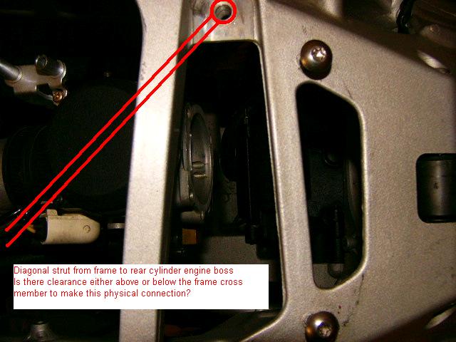 If it was me, then I'd prefer to use a beefier frame boss location instead of those small mount holes for the XB airbox. The frame has some triangulation here in the casting, along with geometry that should help resist motor twisting around longitudinal axis, is that's what the top rear mount is supposed to do. | ||
Sub65chris |
read teh arcives of this post , your idea is covered.  (Message edited by sub65chris on May 20, 2008) | ||
Sub65chris |
the new plan is ot use all three adn run teh tie bar horozontally to the cross member. I will post rough pics later tonight. | ||
Sweatmark |
Guess I must have missed the deal-killer after 2x re-reading. If the issue is strut angle, then gotta ask a more basic question: if the motor has flex along an imaginary axis that connects the front top isolator and rear transmission isolator, then how much lever arm does something attached to that rear top cylinder mount really have? Or just how much resitance to longitudinal twisting (roll) will a strut provide? The lower front engine strut, attached to the XB stabilizing framework, has a large leverage on the longitudinal axis, and the struts at front and rear control rotation around a vertical axis. If the objective is to allow some front-to-back motion, then strut setup shown above is bad idea. If instead some up/down motion flex is desirable, then the above strut would be OK. | ||
Jos51700 |
The only issue with the diagonal strut is that the load is then partially transferred through it, whereas when perpendicularly mounted, the fore-aft vibration of the motor is absorbed in the motion of the strut. In this illustration, you can see how the diagonal strut would fight the motion that the tie-bar would allow. 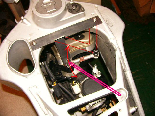 However, the strut from the rear-mount location reinforcing the "fixed" end of the new tie-bar bracket would be good, and also relieve some of the load on the decidedly weak 1/4-20 screws. | ||
Sub65chris |
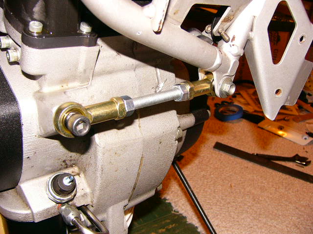 this will be the tie bar 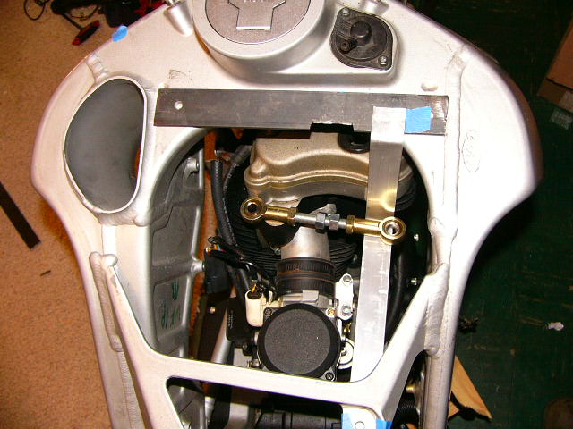 top view the aluminum will be replace by a piece of 1x1 angle iron 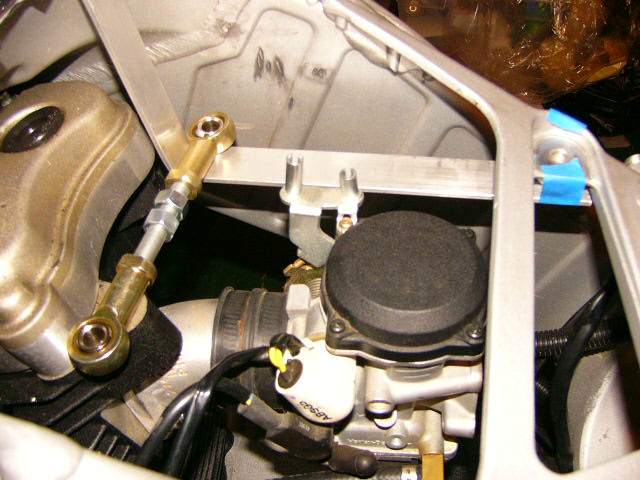 side view for perspective | ||
Toona |
I believe you'll need a little lateral support for the tie bar mount to not flex 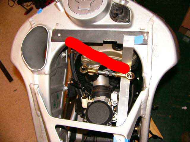 I believe you were going to already add this brace (from prior pictures), but just didn't add it to the mock up aluminum brace. | ||
Diablobrian |
Be sure to use grade 5 or better bolts to mount it. Most stainless screws and bolts will shear very easily when subjected to dynamic loads, and use either shoulder bolts or bushings on the bolts that go through the ends of the tie rod or they will get sloppy really quickly as the threads wear down. I'm sure that you already know all this, but I figured it would be worth mentioning. | ||
Sub65chris |
yep guys, I added the brace last night. and I have some grade 8 bolts adn screws I am using for all of my fasteners. I am going to north dakota this weekend and I will be using my dads shop to build the actual mount. his welder is smother running and he has all the bandsaws and crap that will make this easier than using my dremel. plus i think I can bum the angle iron I will need. (Message edited by sub65chris on May 21, 2008) | ||
Jos51700 |
I am impressed with your front tie-bar! | ||
Wantxbr |
I like that support. Mount is looking good. | ||
Ezblast |
Sweet - when you get that done - the rear mount - could you give the dimensions and materials used, and where did you get those tie bars? EZ | ||
Fastxb12r |
Sub65chris I love what your doing keep up the good work and I cannot wait to see it done maybe even a video of it going around the curves.  | ||
Retrittion |
Man, I really want one! Can't wait to see the finished product. | ||
Sub65chris |
napa - part number 732-1129 "rod end" and fine thread rod with two jam nuts. total cost is anout 16 bucks for the tie bar. I will need to make another and the second will be less because I cna use the left over rod. I will post dimensions when the mount is complete. | ||
Jos51700 |
Man! That's a good price for rod-ends! I'll hafta remember that! | ||
Wantxbr |
Chris you better put up videos of your bike so we can see and hear it go down the road. | ||
Sub65chris |
when the thig gets done or while it is still in the basement? | ||
Retrittion |
both...please? | ||
No_rice |
Matt was saying how it sucked that he was going to have to disassemble it to get it out of the basement, i'm like bullshit you are! i know they fit through a walk in door and 2 of us can get that thing out of there! | ||
Ezblast |
I'm sure you can - I pick mine up all the time to move it around by the frame - two guys can handle it easily - this is terrific, since I'm almost done rustling up parts for my own project Blast - you bet I'm taking notes! This is a terrific thread! EZ | ||
Jos51700 |
I was thinking 'bout this last night while I was sleepin'. You could, if it's not too late, bring the forward and rearward mounts of the brackets over the edge of the frame, and make it a tight fit (With hard rubber or plastic padding to avoid abrasion), so the frame would take more of the fore-aft load, and the bolts would be loaded less in-shear. Then you wouldn't be transmitting load through the front bolts to unreinforced parts of the frame.... Just an idea. Not sure what you guys think Hard-to-understand drawring: 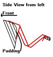 (the black part of the drawing is the frame) A fella could even triangulate the two diagonals if he wanted. I drew them thick because you'd said you were using angle iron. | ||
Sub65chris |
yeah I was going to use something like thick innertube or other abbrasion resistant rubber to keep the iron from cutting into the frame. I will post pictures as I install . | ||
Ezblast |
 | ||
Point_doc |
From looking at the drawing, it needs a gusset or else it will permit movement or even fold upon itself or break from the back and forth motion. A gusset is a device, often triangular, used to reinforce a connection between two components. (Message edited by point_doc on May 22, 2008) | ||
No_rice |
it is going to be made out of angle iron which will add more strength than it will need! |