| Author | Message | ||
Captain_america |
I brought something new to the table? YEAH! Danny, Yeah high beams kill that poor little battery even in my CR, and thats... what, 3-4amps extra draw with my DDM 55w high beam HID? voltage vs. fuel flow IS significant... I see this and all kinds off drivability issues arise with the EFI systems I tune on  "cagers" when voltage fluctuates even one volt. Fuel line pressure, pump flow, and injector output are all effected resulting in inconsistent air fuel ratios. "cagers" when voltage fluctuates even one volt. Fuel line pressure, pump flow, and injector output are all effected resulting in inconsistent air fuel ratios. The 1125 fuel system is returnless right? thats even worse! I know standard fuel pressure is usually around 43.5 PSI on a normal port EFI system. If the 1125 ECU does not make up for these crazy a$$ battery voltages just think at what the air fuel ratio is doing based on what the voltage happens to be at the time of a dyno run. Maybe someone should stick a battery charger on the bike when dyno'ed? ps. that's not the 1125 fuel pump graph but a very commonly used, high quality aftermarket EFI pump capable of 700hp | ||
Boogiman1981 |
here's the fun part capt all of the sensor outputs are affected by lowering the voltage. not jsut fuel output from the pump. | ||
Captain_america |
Yes Boogiman, you are right, but nothing is as effected by voltage as the fuel system because it runs off of battery voltage while sensors generally run off 5 volts... | ||
Fast1075 |
Yet another person steps up with the ability for abstract thought....bravo!! The knowledge curve just took another upswing. | ||
Reepicheep |
Even at 12V and 1 amp, the pump can deliver 5 GPH and is at something like 135 PSI. The gallons per hour are at least twice what the bike can use, so that doesn't seem to be an issue. And I'm guessing 135 PSI is more than enough for the fuel injectors to work right. There must be a fuel pressure regulator somewhere in the system... either in the fuel pump, or some kind of mechanical regulator in the injectors or somewhere in between. | ||
Avc8130 |
The ECM has programming to adjust fuel pump for battery voltage. ac | ||
Tpoppa |
My voltage Directly corresponds with engine temp. A hot engine >190 really doesn't charge well regardless of rpm. I can rev the hell out of my bike in low gear, but if the bike is hot, its not gonna charge. Plain and simple. The ecu must determine whether or not to have the 3rd leg on based on CT. If my CT is in <185 it will charge at 13+ volts all day long at 3k. And... even though at a higher rpm the load on the motor is less and vacuum is high and fuel delivery is low; the CT will run hotter than if at the same speed you clicked up two or three gears, let the CT come down then you'd be charging again... This is most noticeable with my high beams on (which I prefer on 100% of the time). I'm pretty sure this is because of the cooling fans. With the current ECM flash...CT around 180 degrees the 1st fan kicks on, CT around 205 degrees the 2nd fan kicks on. With both fans running, mine rarely gets above 12.9 even at hwy speed. | ||
Captain_america |
The ECM has programming to adjust fuel pump for battery voltage. ac Whew! Ok so we can all go back to winding our stators again... false alarm haha On the way to work this morning... Turned the key on, Batt light was on so I let it sit for a minute to bring the voltage down some. Fired her up and as soon as the cold warning went away I switched to display voltage and it was at 14.5! at idle, 160 CT. Start down the street (25mph) and flip on the high beam and voltage doesn't even quiver. CT hits 172 and I think I hear one fan turn on, voltage still good. Start on the highway and CT hovers around 170 and voltage is >14 no matter the rpm. after 65 miles of the boring freeway I pull off after drafting behind a work truck for some time, sitting at the light CT is 190 and 12.2 volts. Well shit, so I turn the high beam off and voltage starts to rise as soon as I take off. Anyway, I think Tpoppa makes a point too that the fans are effecting the voltage in relationship to CT, I just cant tell when they are running or not when I'm moving (I wear ear plugs) If you can keep the CT down it will help the charging system, lower rpm = lower CT. | ||
Fresnobuell |
If you can keep the CT down it will help the charging system, lower rpm = lower CT. I have had the harness for less than 24 hours, so I am still making my first observations, but I noticed the same thing Capt. did yesterday. On a cool motor, the harness was charging at 13.9 for a short period of time. Surprised me as my RPMs were low at about 4K. What we need to find out is the drop in voltage caused by add'l electrical load (via cooling fans, etc.), the new stator logic or possibly just the fact a hot stator will produce less energy. I doubt it's the latter as I noticed at least .5 to .6 volt drop post-harness under identical conditions. The harness-ed voltage seems to be more variable, so the harness is doing something for sure (unless I am just paying more attention to it.) | ||
Hootowl |
You can't use ohms law when dealing with inductive components. The stator is composed of several inductors. An inductor is a device which opposes a change in current. When each inductor discharges, it attempts to maintain its current amperage output. As the load decreases (increased resistance) the voltage across the windings has to increase to maintain the current flow. A shunt type regulator will burn up if you attach it to a stator that is capable of putting out more current than the regulator can thermally handle. All of the energy produced by the stator that is not used by the bike's electrical loads is converted to heat in the regulator. More power = more heat. I get what you're saying about the load determining the current, but the load in this case is a shunt to ground through the regulator. It isn't a direct short, that would burn up the stator, since its internal resistance would be the only place there is any power to heat conversion taking place. But the shunt is a path to ground (its resistance is dependent on the current electrical load of the bike) and will draw as much current as the stator will put out. It has to. Think of the regulator as a variable voltage divider. If the bike is drawing very little current, the regulator decreases its internal resistance to draw more current so that the voltage available to the bike remains at 12 volts. As the bike's electrical load increases (less resistance) the regulator increases its resistance, reducing the current, and maintains 12 volts at the output of the regulator. Were it not able to adjust its internal resistance, the voltage available to the motorcycle would vary with the load. The stator and the voltage regulator have to match. Too large a stator would burn up the regulator. In the case of the 1125s however, it appears that the bike's electrical system draws just about as much current as the stator can put out, which means the regulator isn't having to dissipate much heat at all. A higher capacity stator should pose no issues. | ||
Tpoppa |
Howtool, good explanation. The stator and the voltage regulator have to match. Too large a stator would burn up the regulator. In the case of the 1125s however, it appears that the bike's electrical system draws just about as much current as the stator can put out, which means the regulator isn't having to dissipate much heat at all. A higher capacity stator should pose no issues. 08s & 09s use the same VR even though the 09 stator has 20% more output, 432w vs 520w. I would think the VR is better matched to the 08, since that was the original design. 0n 09s without the harness upgrade, I believe the stator does produce more power/heat than can be managed. The purpose of the harness upgrade is to remove some power/heat from the system at low RPM. With the harness upgrade, the stator is producing barely enough power, or not enough (depending who you ask). As some have suggested, I believe the best solution is to rip out the harness upgrade and a) install 08 stator/rotor, or b) have the 09 stator rewound to produce less power, perhaps a bit more than the 08. | ||
Hootowl |
A non shunt type regulator might fix things too, since the stator wouldn't be at max output all the time. | ||
Hootowl |
Yeah, I meant the 08s. It sounds like they were thinking the same thing when they upped the wattage in the 09. With the fans and highbeam off though, it may be too much to dissipate. | ||
Blk09r |
I just installed one of these in my bike...... 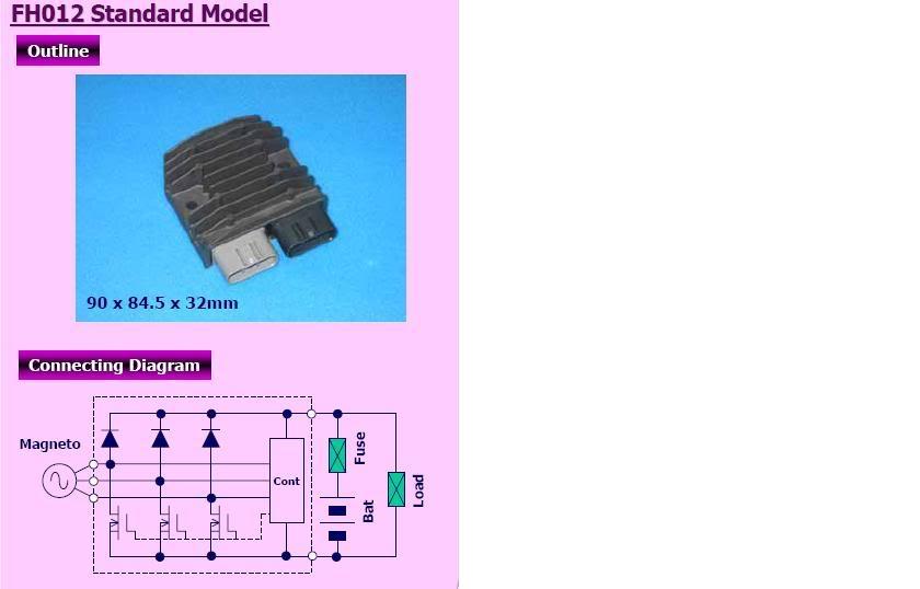 So far so good. I'll write something up with pictures in the next couple of days. | ||
Tpoppa |
Blk, Did you remove the harness upgrade? | ||
Blk09r |
I haven't removed the upgrade yet. I rode in to work this morning and the voltage was between 13.5-14.5 volts with fans running or not. I had to relocate the regulator to under the passenger seat because it wouldn't fit in the stock location. There isn't much air circulation under there so I might find a way to ventilate it. | ||
Reepicheep |
Hootowl... great description, but I saw at least one schematic posted here (not for the Buell, but close) that had an SCR behind a diode. When the voltage was below 13.9 volts, the SCR did nothing, and the diode just prevents the battery from putting current into the stator. When the voltage was above 13.9 volts, the SCR got turned on and shorted to ground and stayed there until the next AC cycle (crank rotation) shut off the flow and reset it. The only time the battery was charging was the short period between when the voltage from the stator exceeded 12.2 (or whatever your batteries quiescent voltage is) and until the voltage hit 13.9 volts. Not a very efficient design, but given a two or three phase stator and a full wave rectifier, it'd do. It also had the advantage that the forward drop when the SCR shunted to ground was 1.2 volts (or whatever an SCR does, I forget). So it dissipated less power (V*I). Were it trying to drop that full 12.9 volts and 20 amps or whatever, it'd be melting aluminum. Which does point out that all that heat has to be going to the stator. Which is why I like the idea of that (probably mosfet based) switching regulator posted above. I also like it because it was a TON cheaper than the stock Harley part. I wish somebody had schematics for the HD voltage regulator. Then we could really answer some questions. | ||
Blk09r |
That reg is mosfet based. I'm surprised at how warm it gets though. It doesn't get as hot as the stock regulator but it still gets pretty warm. | ||
Tpoppa |
Reep, No schematic, but the manual states Voltage Regulator Volts @3600 RPM = 14.3-14.7 Amps @ 3600RPM = 45 amp 3 phase shunt | ||
Dannybuell |
Blk09r - I am excited to hear and see what you have done. | ||
Hootowl |
Reep, I've seen those schematics too. I don't know what type the 1125 uses. I suppose I shouldn't assume it's the same as the sportster. If I remember correctly, and it has been a LONG time, an SCR drops very little voltage when biased on. Much less than a regular old junction type transistor, which, depending on doping, ranges between .5 and .7 volts. Given your field of expertise though, I am probably off base. | ||
Eweaver |
Captain, PM sent | ||
Reepicheep |
My field expertise was looking at one on a meter in college 20 years ago (probably right before I blew it up). Don't defer to it.  Of course we don't have to do actual science anymore... now we have google. Google says .9 volts forward drop.  | ||
Black |
Are we any closer to discovering why stators are failing now, than we were 500 posts ago? Does anybody know how many have failed? | ||
Eece_ret |
Note: I think the MosFet R/R is a GREAT idea!!! Below outlines why I am biased towards it! Let me see if I've got my head around this... Watts = Volts * Amps A fixed mag. stator as found in moto's can generate a range of power (wattage). The voltage at the terminals is linear to the RPM of the rotor within the stator. The maximum amperage of the stator is limited by the diameter and resistance of the wire it was built with and the RPM of the rotor within the stator. !!!!!HEAT!!!!!! The hotter the stator the less efficient it becomes. Essentially as conductors get hot their resistance increases, more resistance within the windings equals a less efficient stator. Heat within the stator has a linear relationship to the amperage (current) being drawn from it. More Amps more heat. This is of special note for at a given load as voltage drops amperage rises. Greater amps at a lower voltage will create more heat within a conductor than a lower amperage draw with higher voltage (given same load). If Heat in the conductor rises so does its resistance, lowering voltage at the terminals, requiring EVEN MORE amperage to be pulled from the stator... Seems like a downward spiral. A stator will happily provide zero watts and create zero heat if no current is being drawn from it. The OEM Regulator/Rectifier (r/r) is a linear shunt type, so the stator is essentially under 100% load 100% of the time (Load current + shunt current = total potential current from stator) If I am understanding it correctly the MosFet based r/r essentially varies the amperage pulled from the stator given load demands and delta V. Seems to me that the switching r/r described above could curtail much of "wear" these stators are experiencing by only drawing current from the stator that is required by the load required by the engine bits and charging system at any given time. Thus minimizing the amount of heat generated within the windings. In low RPM situations I could still see excessive heat build up occurring due to loss of voltage at the stator terminals . However I could see a switching r/r being of benefit here too. When the motor begins to spool up after a low rpm situation the stator will reach a point where energy created will exceed demand. Once this point is reached we should expect thermal savings within the unit, and hopefully a decrease in temp at the windings. If allowed to "cool" enough they may be able to survive these low RPM moments that it does not seem to be able to recover from (in the long run) | ||
Ezblast |
Devil Mountain called and said my bike was fine, though I told them I would pay for an hour, if they would heat the bike up riding it for an hour and then check it. So I'll pick it up tomorrow, and take it for a hell of a ride sunday up and down Morgan Territory road - a highly twisted piece of road - we'll see - but my personal feeling is that the mechanic hit Denny's or a bar for an hour - with the beginning and end miles both logged there better be at least close to 50 or more showing - as I said - we'll see. EZ | ||
Dannybuell |
Eece_ret - Does that translate to EE, CE retired? | ||
Parrick |
Did the FH012 regulator swap a couple of days back. I also disconnected the band-aid harness. So far the voltages stay pegged right around 13.9 - 14.0V during regular operation. Sitting at a long light with both fans running it will dip down around 13.4V. I have no idea if it is keeping the stator temps down but I just don't like the whole idea behind the band-aid harness operation. Hopefully with the stator oil flow blockage removed and a better R/R design in place it will all mesh. Only time will tell. I'm still waiting on proper connectors but here's a couple of pics of how I decided on mounting position. It's a little hard to see the FH012. I mounted it upside down on the bottom of an aluminum crossover bracket under the seat.  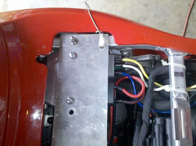 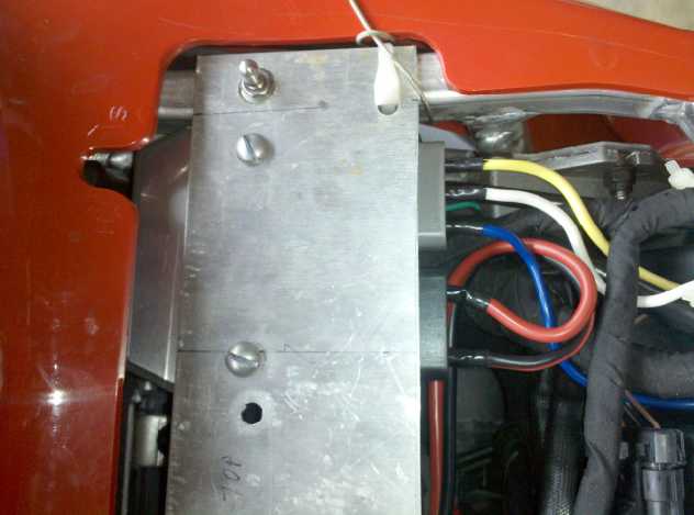 | ||
Dannybuell |
Parrick - Looks good! | ||
Blk09r |
Parrick, very nice. Do you think the regulator will have any heat issues? I just started a new thread on the same regulator installation. |