| Author | Message | ||
Greg_e |
Finally got around to making this post. A few weeks ago I got a "defective" ECM from Skifastbadlyfrom his Uly. So I cut the top off to see what what inside. As usual with this type of device, it was completely filled with a potting compound. In this case it is a rubber compound (thankfully they didn't use epoxy). 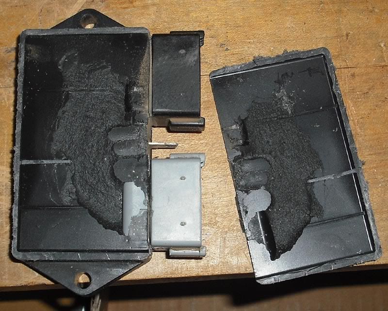 Even though it is soft rubber, these devices are practically "not repairable", took me around 2 hours to get down to board level and get the board out of the plastic.here are the pictures after I stripped most of the rubber off. 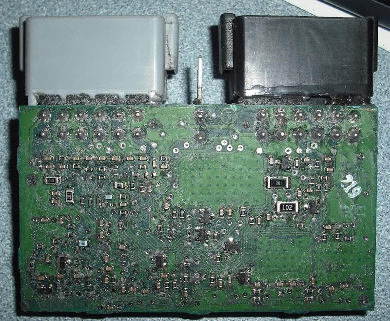 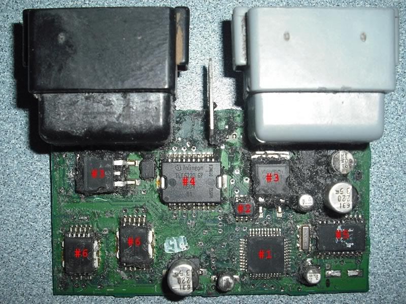 Major component listing: #1 18f452 I/PT MCU running with an 8.000Mhz crystal #2 Microchip 25C320, 4k*8bit serial EEPROM (holding configuration data) http://ww1.microchip.com/downloads/en/DeviceDoc/21227E.pdf #3 VNB49N04 Mosfet #4 TLE6220GP Smart Quad Low-side switch http://download.siliconexpert.com/pdfs/2008/08/14/ urlc/smn/tle6220gp.pdf #5 TLE4470 Low drop out voltage regulator +5 volt #6 VB125ASP High voltage ignition coil driver http://www.datasheetcatalog.org/datasheet/SGSThoms onMicroelectronics/mXywxqy.pdf I'm not certain about #2, can't find an exact match to the letter/numbers printed on it. Hopefully this will help someone to make this machine better, or at least fix them when they "break". (Message edited by Greg_E on December 28, 2009) | ||
Skifastbadly |
That ECM did 23K miles of highly entertaining riding, from ATV trails to 114mph on a deserted Nevada Hwy. It was responsible for the illegal transportation of thousands of dollars of beer from Wyoming to Utah (all for personal use). Kind of creepy to see it all pulled apart like that. The replacement used ECM, with the uploaded map from the old one, has performed flawlessly in the approximate 600 miles I've put on the bike since I did the ECMectomy...so the old one was definitely toast. Thanks for your work on this, but looking at these photos give me about as much of a clue as to how to service one of these as looking at a dissected human would give me as to how to be a doctor. | ||
Greg_e |
Edited the post with new information about component #2, it is what I thought it was but I was having a hard time pulling the part number off the chip (that damn rubber goo gets everywhere). Thanks for the info. I'm hoping this will spark not only the repair of these devices, but a similar device that can be used in its place once the supply has dwindled. The stuff on the back side of the board is all pretty much just glue to hold the other components together. Now that we all know what the basic components are, designing something similar should be within reach. There is a DIYefi system in the works that uses a different MCU, but some things might be able to be borrowed from the stock ECM to make an aftermarket version. There are a few AVR based projects out there, some of them with source code that might be leveraged, and I bet if a person checked the Microchip PIC forums that there are a few PIC based systems out there with code. Cypress makes a few chips that might prove useful too, their PSOC family has some neat features that might make things a little easier to use than a traditional MCU. A 32bit AVR might be neat, and of course there are the different ARM family of processors. Lots of choices and lots of different approaches. I'm pretty sure the Mosfets drive the injectors directly, the smart switch probably runs the relays, and of course the ignition drivers run the two coils. | ||
Reepicheep |
Cool. That 18f452 is a PIC chip. I've been playing with similar chips for a while, they are very accessible to code against. I wonder if they set the bit that keeps you from reading back the assembler... | ||
Greg_e |
From what I was told by someone who has obviously done a lot more work than I have on these ECMs is that the early versions used an 18C452 processor which is OTP (one time programmable), newer ones using the 18F (F for flash eeprom). He also said that the one he tried was locked but he didn't check to see if the bootloader was enabled and if enabled what kind of info you can get from the bootloader. The bootloader could allow complete recovery of the program, or it could only allow new programs to be loaded, depends on the capability of the chip and which fuses are burned. | ||
Greg_e |
I just found out that they used a multi layer PCB for these, so it is basically impossible to know what is happening on the inner copper layers. What this means is that any ECM that has a real crack in the circuit board is less than likely to be able to be repaired. If a schematic was available then you could always run wires from component to component to fix the damage. | ||
Go2 |
Greg, Nice job exposing the circuits Surface mount pcb building is my job. My experience PCBs don't crack. Common is the failure you just found! External connectors stress pins and pull loose at soldered pcb locations. Next, less common are ceramic 0402 and 0603 size capacitors cracking under stress. I only see physical boards fail inter layer is when something shorts and draws excessive current. We all have an arsenal if tricks to find the culprets. Did you notice the 2008 (DDFI 3) and above increased the memory size and Map layout? Wonder why? Jack | ||
Froggy |
Go2, that is probably to support the more advanced fuel injection on the DDFI3 models. They have more precise fuel injection. Also, the same ECM is used on the 1125R models, so it needs to support more values for the higher redline, and read things like the dual O2 sensors and other new sensors not on the old DDFI2 bikes. | ||
Greg_e |
I was told by someone that has done lots more work on this than I have that the inner layers are just ground and +V. Been too busy at work to look into this more and try to fix the one that I have where the black connector is broken off the board or more accurately the board is broken off around the black connector. And since the middle layers are just ground and +V there may be a way to get this working on a 2 layer board which means that real damage can be fixed as long as the MCU is not damaged and can be removed. This is a long term project that will need to wait until other projects are complete. More of a "Oh crap, there are no more ECMs available to buy anywhere" game plan. Need to go through and ID all the components on the bottom, then remove them to get a connection list, and then put everything into a circuit CAD program (like FreePCB) to generate a new board (no copyright/patent issues) and see what it looks like. Might work, might not. That said I still want to get some kind of DIY EFI system working for a direct plug in to the Buell harness, may not be emissions legal, but should help to keep the old bikes running and could be an alternative to the real factory race ECM. | ||
Mesozoic |
Regarding the PIC, you could definitely pull the currently flashed binary out, but it'd be just that... binary. The original source code in C would be super useful... if anyone can get a hold of it, I can definitely figure it all out. |