| Author | Message | ||
Posplayr |
>>>I guarantee that if you don't provide any input, the results that will follow will not be to your liking. >>>>This is your last chance to have input on the rules that will be used to analyze your data. If you decide not to participate, we'll provide the standards by which your data will be judged. This is your last chance to have input. Don't blow it. Bubba, This sound civil? Sounds like a threat to me. Please note that there is a discipline called engineering; perhaps your have heard of it? That is the basis for my analysis and doesn't require any further clarification to anyone familiar and practiced in that discipline. | ||
Timebandit |
You've represented yourself as being an expert, advising people that they should buy a Compufire product. I think that the improvements that the Compufire offers are illusory when it comes to the 1125 application, and it is my intent to prove that. I'm going to be civil and objective in analyzing your data, and I will let the chips fall where they may fall. There is nothing personal about this, so you have no reason to feel threatened personally. But be advised that I intend to use your own set of data that you collected to prove a point -- the end result is going to be that nobody who owns an 1125 is going to consider it worthwhile to spend $200 to buy the Compufire product. When we're done analyzing this data, it will become obvious to everyone that the Compufire product doesn't bring anything meaningful to the table that 1125 owners don't already have. I'm giving you one last chance to provide definitions to create the rules by which your data will be judged. I do this because I want to be fair and objective. I'm going out for dinner tonight. I hope we'll have some rigorous definitions to guide us by the time I get back. If you're not willing to provide them, I invite anyone else to offer answers to those 5 questions and we'll proceed to use the best ones that are made available. (Message edited by timebandit on June 11, 2012) | ||
Dannybuell |
I had a chance to work at Intel years ago when they were cranking out millionaire engineers with masters degrees in seven years. My experience there was the ideal of an extremely polite and challenging workplace. The difference between sink or swim? As a contractor at Intel, I was invited to an employees only meeting where the discussion was centered around who the group liked and and didn't like. After the meeting my boss asked me what I thought, I said it sounded like a popularity contest. I was then told that all of the candidates were extremely qualified and that their personalities were the only thing left to discuss. You don't have to be a subject matter expert to know who the better swimmer is here. | ||
Nightsky |
Timebandit has questions above. 1) Define series regulation. I think typically of a variably conducting transistor in series with the load, regulating load voltage. There can be substantial voltage drop across the transistor. There also are PWM (pulse width modulation) schemes which vary duty cycle to the load. A series switch turns on and off bang/bang, and average on time determines average voltage at load. These schemes typically have hysteresis between the on and off thresholds. 2) How to identify shunt regulation using an oscilloscope. Shunt regulation has a transistor shunting excess current around the load to ground. Source drives load directly. One indication of shunt regulation is output voltage clamped at a fixed level. 3) How to identify series regulation using an oscilloscope. For linear regulators a pass transistor between source and load can have a substantial voltage drop across it. PWM series regulators will vary duty cycle or "bang on/bank off" between source and load. Pulse width can vary, or some pulses may be skipped. 4) How to calculate power dissipation in the stator. It must involve the open circuit stator voltage. Need to multiply instantaneous values. 3/2 accounts for 3 phases, but is just a constant. stator heat = (3/2)*(Open_Circuit_stator_voltage - stator_loaded_voltage)* stator_current It's pretty tough to directly measure since we can't sample OC stator voltage and loaded stator voltage at the same time. The loaded stator voltage likely will be shifted in phase. Measuring open circuit stator voltage separately and assuming no phase shift is probably good enough for this informal forum. If you shorted the stator to 0V, it still would run hot due to all that current through internal winding resistance and iron saturation losses. Simply multiplying measured voltage * current as in the red plot would yield 0W, so that isn't the right equation. 5) How to calculate three phase power delivery to the load. We've already got that in the red plots. By "load" we can mean shunt vreg dissipation (if there is one) + bike load. (3/2) * stator_voltage * stator_current. | ||
Posplayr |
In response to Nightsky. 1) Define series regulation. Will not disagree with that characterization but in the case of the CE and Compufire SERIES regulators the SERIES REGULATION is restricted to regulators that A.) SYNCHRONOUSLY rectify the 3 phase AC(to eliminate power dissipation of a full wave rectifier) and B.) SYNCHRONOUSLY disconnect the stator from the load to control the applied Battery voltage. When you disconnect the stator leg from the load there is a corresponding drop in current, power, and heat dissipation in the stator. The CE connects the stator to the load using SCR's (I know because when I called to tech support I had the opportunity to talk to the designer and he told me he used SCR's)disconnects the load. The Compufire uses MOSFETS as can be seen by comparing the low voltage drop between the flattop voltage stator and the output battery voltage. In this context SYNCHRONOUSLY means in sync with the stator voltage wave forms. 2) How to identify shunt regulation using an oscilloscope. SHUNT REGULATION in this context means only one thing, shorting the stator legs together with a semiconductor device. When measuring the leg to leg voltages a short is a zero voltage across the legs. Careful to read the words precisely; zero volts can also occur during normal 3 phase full wave rectification into a battery. I showed a reference and I am still waiting from you (Nightsky) to acknowledge this. So the only way to know if there is SHUNTING going on is to compare a rectification wave form to a rectification waveform with SHUNTING. You can also measure the current, but as can be seen in the plots the stator currents are going haywire during shunting with a large scale slow oscillation with the normal stator AC current fluctuations riding on top. 3) How to identify series regulation using an oscilloscope. In general this is harder to identify unless you restrict the SERIES operation to what I defined above. Then SERIES regulation is easy to identify as the voltage goes to the OPEN LOOP voltages, Current goes to zero and the instantaneous power goes to zero. 4) How to calculate power dissipation in the stator. An exact measure of absolute power in the stator Power in the stator can be measured by measuring the phase to neutral voltage across each phase combined with the measured current through that phase. There generally is no neutral tap of a 3phase stator for a motorcycle so the next best thing is measure the relative power under SHUNT regulation compared to SERIES regulation by comparing average current under the two regulation modes. Each measurement can still be related to stator power but it is indirect estimate. P=I^2*R(est) per phase; The estimated power in the stator is provided in the summary performance charts. 5) How to calculate three phase power delivery to the load. Yes as I previously stated. | ||
Hildstrom |
Timebandit wrote: "My name is not Bubba. Be aware that it's not a good idea to proceed with personal attacks, name-calling, etc., as that kind of activity can get anyone banned. It also lowers your credibility when you have to resort to personal slurs." Haven't you repeatedly referred to Posplayr as PoS (nasty acronym?) and as a Compufire pimp? Please practice what you preach. Timebandit wrote: "There is nothing personal about this... But be advised that I intend to use your own set of data that you collected to prove a point -- the end result is going to be that nobody who owns an 1125 is going to consider it worthwhile to spend $200 to buy the Compufire product." How can you possibly perform unbiased analysis or experimentation when you are certain you already know the outcome? Posplayr: Thank you for performing measurements, publishing experimental data, and interpreting your results. The rest of your graphs beyond 1500 rpm clearly show that one regulator is shunt and the other is series. These graphs beyond 1500 RPM clearly show reduced stator current from the series regulator. | ||
Posplayr |
Thanks Hildstrom  | ||
Timebandit |
It's easy not to be biased. I'm not designing the experiment, or collecting the data. I'm only going to look at his data, and analyze it using an unbiased set of rules to interpret it. To make the analysis totally fair, I'm asking him to define *ALL* of the rules by which his data will be analyzed. By allowing him to set the rules for how the experiment is designed, how the data is collected, and how the data is interpreted, I only act as an unbiased person following his instructions, following all of the rules that he has laid down to render an accurate, truthful answer. But we've seen that he is not willing to participate in creating a totally objective format for analyzing his data. He wants to avoid setting up the criteria for an objective review of the product that he's been actively promoting. He wants to avoid participating in making an unbiased set of rules, because he knows that in the end the analysis will not be favorable to the Compufire, and when that happens he wants to have the ability to claim that the entire process was unfair. The whole purpose of asking him to define the conditions by which his data will be interpreted is to insure objectivity and eliminate the possibility of bias on anyone's part. If I'm doing anything, I'm offering him the opportunity to stack the deck in his favor. There is another reason for him to refuse to answer those simple engineering questions -- perhaps he can't answer them. It's evident from his published data that he does not know how to calculate power dissipation in the stator, because his power dissipation calculations are all wrong. By refusing to answer the questions, it looks like he doesn't know how to properly define the different ways in which series regulation can be implemented, and how the scope traces would look under each type. Those aren't the kind of responses that I would expect from someone who represents himself to be an "expert". He's been rendering "expert" opinions that one specific product is better than all the others in the marketplace. Well, if he's such such an expert, it shouldn't be at all hard for him to answer a few simple questions. But he won't do it. Why? The refusal to answer makes it seem as if he is a fake, and that he's not the expert he claims to be. Either that, or that the Compufire product he is promoting is not as great as he claims it to be. I just want to make sure that people on this forum don't get conned into wasting their $200 to buy something that isn't going to help them. That's my objective in this thread. | ||
Timebandit |
The analysis of the CF regulator that will follow is going to require several posts to display all of the images. I'd appreciate it if everyone could avoid interjecting their comments until all of the photos are up. | ||
Timebandit |
looks like there's going to be a wait while i have to resize a bunch of images... Edit: I'm going to move the images in the following posts to photobucket. The non-standard encoding methods and the restrictions on file size are a hassle to work around. I like photobucket better. From now on, I'll be posting the rest of my photos through photobucket, so I'm going to consolidate everything in one place. (Message edited by timebandit on June 12, 2012) | ||
Timebandit |
Pos wrote:
I'm going to follow the exact methods that Pos has suggested, and compare a rectification waveform produced by a known shunt regulator to the regulation waveform provided by the Compufire. Here is a reference example for SHUNT regulation. This is Pos' plot that shows the Shindengen FH012AA shunt regulator acting to actively regulate the output to the battery at 13.7 volts. Image is on photobucket: http://s1161.photobucket.com/albums/q519/timebandit6/?action=view¤t=01--shunt-2k.gif (Message edited by timebandit on June 12, 2012) | ||
Timebandit |
The following graphic depicts a direct comparison of the Shindengen Shunt regulator to the Compufire at 1500 RPM. In the original graphic the title was provided as, �Non Regulating Comparison.� That title is misleading. In this graphic, both rectifiers are acting as SHUNT regulators according to the waveform comparison criterion that Pos has specified. Image is on photobucket: http://s1161.photobucket.com/albums/q519/timebandit6/?action=view¤t=02--shunt-compare2.gif Notice that in each case, the regulator's output voltage is clamped to 14.2 volts, which is in excess of a fully charged AGM battery's resting potential of 12.6 volts. Also notice that in each case, the waveforms for current are identical. Current is being allowed to flow at all times, while the stator voltage is being clamped to 14.2 volts. This is the hallmark characteristic of SHUNT regulation. In this picture, both regulators display identical waveforms. According to Pos criteria, both are acting as SHUNT regulators, and both are dissipating equal amounts of heat into the stator. For this reason, the chart's original caption of �Non Regulating Comparison� is misleading. A more accurate title for this graphic would be �Shunt Regulating Comparison.� At this RPM, which corresponds to idle RPM on a Buell 1125, the Compufire acts just like any other shunt regulator and offers no protection to the stator. This observation will become very important later, where I will use Hildstrom's temperature data to support Harley-Davidson's assertion that the primary area of risk to the stator is in the zone of low-RPM operation. Again, in this high-risk area, the Compufire product offers no protection to the stator. (Message edited by timebandit on June 12, 2012) | ||
Timebandit |
The next few images will use snippets from Pos' own charts to show periods in which the Compufire product behaves exactly like a conventional shunt regulator. There are some areas i which the Compufire's waveform will be different � I'll address those with images that will follow. For the time being, I'm going to guide you through a number of graphics which demonstrate that the Compufire regulator acts EXACTLY like a conventional shunt regulator during most of it's operation. I'm going to use Pos' own waveform-comparison critera to establish this similarity. The following graphic is a cut and paste of Pos' oscilloscope tracings for both the Shindengen Shunt regulator (left) and the Compufire �Series� regulator (right), with both operating at 2000 RPM. Image is on photobucket: http://s1161.photobucket.com/albums/q519/timebandit6/?action=view¤t=03--composite-2k.gif Notice that both regulators are clamping the yellow voltage output to ~14 volts (13.7 volts to be exact), while allowing current flow to remain unimpeded (blue sine waves). In these two examples, the waveform comparison criterion tells us that all of the waveforms look like shunt regulation. Using Pos' criteria, we can conclude that BOTH regulators are acting as SHUNT regulators during the intervals displayed on the charts. (Message edited by timebandit on June 12, 2012) | ||
Timebandit |
The next image is the same side-by-side comparison at 4000 RPM. Just as before, the charging system's output voltage is being clamped to ~14 volts (yellow) while current flows freely at all times (blue). If we look at these two regulators as black boxes, and don't pay attention to what's inside, they both appear to be working in an identical fashion; according to Pos' own waveform-comparison standard, at 4000 RPM both of the SHUNT regulator on the left and the �series� regulator on the right both appear to be acting as SHUNT regulators at all times shown in this graphic. Image is on photobucket: http://s1161.photobucket.com/albums/q519/timebandit6/?action=view¤t=04--composite-4k.gif (Message edited by timebandit on June 12, 2012) | ||
Timebandit |
The next image is the same side-by-side comparison at 5000 RPM. Just as before, the charging system's output voltage is being clamped to ~14 volts (yellow) while current flows freely at all times (blue). Both the SHUNT regulator on the left and the �series� regulator on the right continue to be acting as SHUNT regulators. We're not seeing any �series� regulation yet. Image is on photobucket: http://s1161.photobucket.com/albums/q519/timebandit6/?action=view¤t=05--composite-5k.gif (Message edited by timebandit on June 12, 2012) | ||
Timebandit |
The next image is the same side-by-side comparison at 6000 RPM. At this RPM we don't have a trace of the Shindengen Shunt regulator to use for comparison. All that we have is the Compufire. If we temporarily restrict our look at the Compufire's behavior to the waveforms that are shown in this graphic, at 6000 RPM the underlying method of operation for the Compufire continues to be SHUNT regulation, as defined by the continued clamping of the output voltage to ~14v (yellow) and by the passage of current during 360-degrees of rotation (blue). Image is on photobucket: http://s1161.photobucket.com/albums/q519/timebandit6/?action=view¤t=06--composite-6k.gif According to the waveform-comparision critera provided by Pos, these images have shown that the underlying method of operation for the Compufire system is one of SHUNT regulation. Now we'll look at some additional charts to see how the Compufire changes it's behavior at certain times in order to provide what Pos is calling �series� regulation. (Message edited by timebandit on June 12, 2012) | ||
Timebandit |
This image is Pos' screenshot of the Compufire in operation at 2000 RPM. Image is on photobucket http://s1161.photobucket.com/albums/q519/timebandit6/?action=view¤t=07--ssr-2k-shutoff.gif Notice that near the middle of the screen something different happens. The Compufire switches off the connection between the stator and the load. The disconnect/shutoff is indicated by the following three observations: A) the blue sine waves that represent current flow become flat lines. No current is flowing from the stator to the battery through the regulator; B) The red lines, which are intended to approximate power flow into the regulator/battery, become flat lines; C) The stator voltage stops being clamped to 14.2 volts, and is allowed to return to a free, unclamped high voltage AC waveform. Measuring the height of the yellow AC waveform, we see that it is about 40volts peak, or 80 volts peak-to-peak at 2000 RPM. Remember this number � it will be important later. What we see in the operation of the Compufire is that it acts as a shunt regulator that is connected to a switch, and the switch intermittently shuts off the shunt regulator. According to Pos, turning a shunt regulator on and off amounts to �series� regulation. It's interesting that Nightsky previously asked whether the Compufire regulator used bang-bang regulation. Antique automobile regulators provided regulation by turning the regulator on and off in a bang-bang fashion. In this case, it looks like the Compufire is doing nothing more complicated than to intermittently switch-off a shunt regulator. Bang! (Message edited by timebandit on June 12, 2012) | ||
Timebandit |
This image is Pos' screenshot of the Compufire in operation at 4000 RPM. Image is on photobucket: http://s1161.photobucket.com/albums/q519/timebandit6/?action=view¤t=08--ssr-4k-shutoff.gif In this diagram, we see that the Compufire product continues to operate as a shunt regulator that is being switched on and off. When it switches off, the unloaded stator voltages return to an voltage of 70 volts, or 140 volts peak to peak. Notice that the Compufire began being switched off at 2000 RPM, and it is being switched off more often at 4000 RPM. These last two images tell us that the �black box� behaves as if it is a shunt regulator, which lies in series with a transistor/switch. The switch varies the regulator's duty cycle by intermittently turning the connection to the stator on and off. We've seen this behavior before. The Harley-Davidson charging system update (aka �relay-harness�) for the 1125 works in a very similar way. At 2000 RPM, it starts to drop conduction out of 2/3 of the stator to limit the amount of heat that is dissipated within the stator at low RPM. (Message edited by timebandit on June 12, 2012) | ||
Timebandit |
This image is Pos' screenshot of the Compufire in operation at 5000 RPM. Image is at photobucket: http://s1161.photobucket.com/albums/q519/timebandit6/?action=view¤t=09--ssr-5k-shutoff-1.gif At 5000 RPM we continue to see the exact same behavior. When it switches off, the unloaded stator voltages climb to an AC voltage of ~86 volts, or ~172 volts peak to peak. The Compufire appears to be nothing more complicated than a compuer-controlled switch that intermittently turns the stator on and off. Compare this to the 1125 harness update: It uses a computer (ECM) to control a switch (relay) that intermittently turns the stator windings on and off. These two devices use different physical embodiments to achieve the same basic result. If we rely upon the waveform-comparison criteria that Pos proffered, then by definition the Compufire is a duty-cycle modulated shunt regulator. The 1125 charging system harness update is also a duty-cycle modulated shunt regulator. If we're going to call the Compfire a �series� regulator under these definitions, then we have to extend that same definition to the Harley-Davidson charging system harness update, and concede that when the Ducati shunt regulator is connected to the ECM and a computer controlled switch (relay), the Ducati/ECM/harness combination is also a �series� regulator. (Message edited by timebandit on June 12, 2012) | ||
Timebandit |
This image is Pos' screenshot of the Compufire in operation at 6000 RPM. Image is at photobucket: http://s1161.photobucket.com/albums/q519/timebandit6/?action=view¤t=10-ssr-6k-shutoff.gif This picture shows the same things we've seen before. In this case the unclamped stator voltages rise to ~104V, or ~208V peak to peak. Notice that when the series regulator disconnects, the unloaded stator voltages have climbed from peak voltages of 40V to 70V to 86V to 104V � in compliance with Faraday's law. Those are the results that I predicted would happen. Those are also results that Pos said would not happen. In this graphic we see that at 6000 RPM duty cycle is being varied to provide more off-time for the regulator at high RPM. That is the secret for why the regulator runs so cool. It runs cool at 6000 RPM because 50% of the time it's turned off. Compare that to the H-D relay harness which shuts of 2/3 of the stator windings. It's turned off 66% of the time. (Message edited by timebandit on June 12, 2012) | ||
Timebandit |
Now let's discuss some of the weaknesses and problems that a user might encounter when installing this �series� regulator. We know that shunt regulators are very hard on stators. We've seen that during much of the operating cycle, the CF �series� regulator basically acts in shunt regulator mode. Then, as RPM climbs, the regulator begins to skip-regulate by intermittently turning the regulator on and off. To understand this effect, you might want to think about how the Buells skip-spark when the motors begin to run hot � the Buells will continue to provide fuel to the engine, but instead of igniting the fuel with a spark, the ECM will skip-spark. The result is that the fuel will not be burned. It will pass through the engine, evaporating, and acting as a coolant to remove heat from the engine. Skip-regulation works to cool the electrical system by not providing regulation during rest periods. That's great if you're in a low-load state. For example, if you're running a bike with no add-on electrical accessories, you can imagine that with such a low load, an electrical system that is only turned on 50% of the time might be able to meet the DC current demands of the bike without any problem. But what happens to those guys who need to run heated gear? If you need full-ouput from your charging system, then the regulator won't be able to exercise the convenience of skip-regulating, and turning the power off half of the time. If your system load is high on the bike, the regulator is going to have to NOT skip-regulate; it will be forced to operate at a higher duty cycle. At high loads, the Compufire can't go skipping cycles. It has to run the shunt-regulator full-on at all times. In that case, it won't be running cool. It will be running just as hot as any other shunt regulator, and it'll be just as hard on your stator. In other words, the Compfire can't help you if you're going to run a high load, because a high load will make the duty cycle approach 100%. The CF won't be able to skip, and when that happens it will get hot. Even worse, if it goes back to full-time shunt regulation mode under periods of high load then it's going to assassinate your stator just like any other shunt regulator. The data appears to suggest that the CF regulator functions like a conventional shunt regulator that's turned on and off by a computer controlled switch. That's probably what the Compu-Fire name is intended to convey -- that a computer is deciding when to fire the regulator and when to turn it off. This method of operation will help someone who puts a low load on their stator, because the device can skip-regulate during periods of low demand. It's not such a great solution for anyone who needs to run a high load, because a high load will require the regulator to stop skipping so often, and move toward a 100% duty cycle. When that happens, it's hard to imagine that this product works any differently than a conventional shunt regulator. Of course, I have to concede that varying the duty-cycle in a low load application is a very smart idea. It's a great way to take away much of the disadvantages that come with a shunt regulator. To accomplish this same goal, Harley-Davidson designed a �series regulator� using the 1125 ECM, an add-on relay harness/switch, and a Ducati shunt regulator to lessen the loads on our stators. It's a mystery to me why anyone would want to spend $200 to buy the Compufire product, when it essentially duplicates a function that our bikes already have. This analysis shows that we'd all be 'd be better off just keeping the Ducati regulator and spending our next $200 bucks to buy the EBR oiling rotor. It will squirt oil on the stator to cool it. And it will do that all the time, regardless of whether you're operating in a high load or a low load state. If the CF regulator were the be-all, end-all answer, EBR would be telling us to buy it. But they're not. They're telling us that the oiling rotor is the answer, and when critically reviewed, Pos' own data that he uses to promote the Compufire tell us that what we really want to do is to buy the EBR oiling rotor. Like I said before: TRUST EBR. | ||
Dannybuell |
sweet! | ||
Sparky |
Very intelligent and informative analysis, Timebandit. It seems like every time I visit the Stator/Voltage Regulator/Charging System subforum, I learn something new every day... And that's a good thing! One thing for sure, I'm saving my money for the EBR oiling rotor mod and hoping that my latest stator won't crap out down the road with it installed. | ||
Timebandit |
POS wrote:
Incompetence? I don't think so. (Message edited by timebandit on June 11, 2012) | ||
Posplayr |
Babba, I'm glad you posted this. You have acknowledged (by it's use) that the data I took a was not fabricated. I'm glad you went through each plot because your detailed analysis exposes your lack of understanding. For me at least that is very amusing. It is amusing because of the glorious style (there has never been a drama queen that would have anything on you) you have used to in providing detailed analysis in support the concluding the obvious. It is now very clear to me that you don't know how to identify shunt regulation. That is pretty amazing because it has all the sophistication of putting a screwdriver across the terminals of a battery. Well of course SHUNT and SERIES look the same when NOT in regulation. That has been repeated numerous times. Well of course a Buell 1125 owner should an get some oil on their stator. That is the only way that the stator will survive. It is kinda comical how you plead for everybody to put their trust in EBR when they designed a bike with a dry stator. Well I guess EBR have learned alot more since 2009 when they came out with this bike. And gee whiz Bubba I guess we will all have to agree that if there is not much difference in a SHUNT regulator and a SERIES regulator when there is yet a third regulator opening windings with a relay based on ECM RPM. Yes if you disconnect the stator from the regulator then it DOESN'T MATTER if the R/R is SHUNT or SERIES. On but by the way the HARNESS mod would have to be considered as SERIES regulation. What is really telling is the length you will go to to demonstrate that you are right. After constant badgering from you about the invalidity of measurements from a 30 year Suzuki (which were restricted to how the regulator/stator worked) you have now jumped on the band wagon to suggest that prediction of the total thermal performance of a 1125 Buell can be predicted using this information. Well if that is not an ABOUT FACE I don't know what is. The only thing that you failed to mention is the overall performance predictions I posted with regard to the difference between SHUNT and SERIES. Obviously this is without a Harness modification. You still have no clue as to how this data was computed do you? 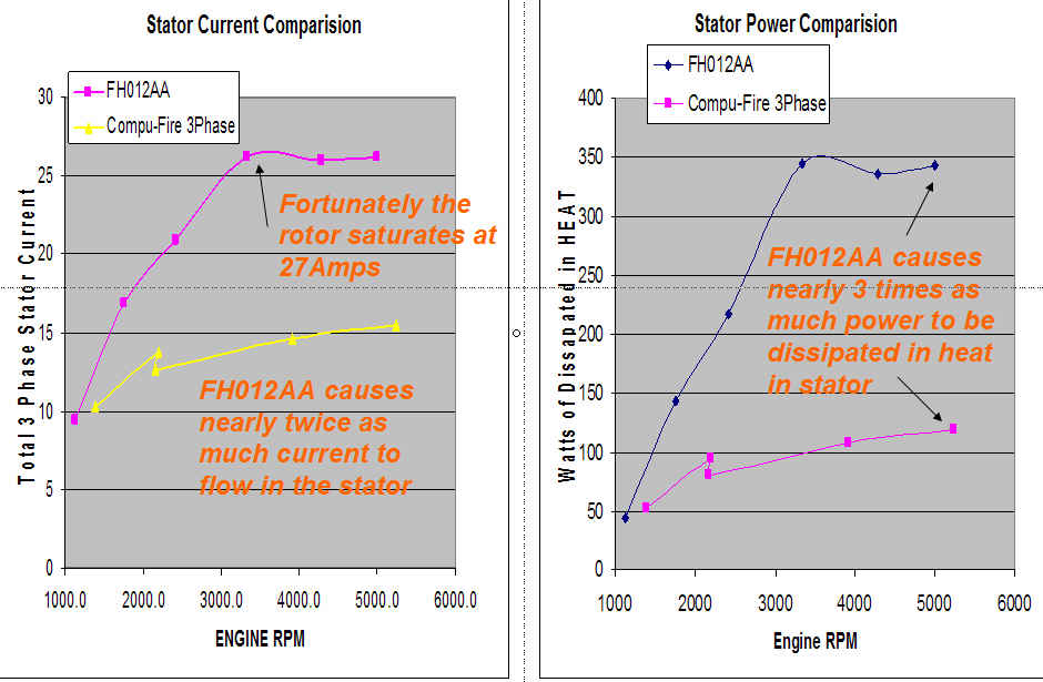 | ||
Curve__carver |
Based on last exchange (and this entire thread) TB wins the internet drama queen award. Congratulations!!! | ||
Timebandit |
The conversation taking place in this thread has clearly established that everyone's level of sophistication on this subject goes beyond "putting a screwdriver across a the terminals of a battery." That was an incredibly foolish thing to say. I can only assume that you intend to be offensive in saying that. It reflects poorly on you. Regrettably, you seem to be continuing in an effort to obfuscate the facts about shunt regulation, when you say things such as "series and shunt look the same when not in regulation." What you're attempting to imply is that no regulation ever takes place, except at those times during which the Compufire is skip-regulating and disconnects the stator from the rest of the charging system. That's interesting, because during those times during which you claim that the Compufire is regulating, it is actually disconnected, no current is flowing to the bike, and it is doing NOTHING. You claim that there is "no regulation" until the CF shut's off the stator, and that when the stator is shut off, THAT is when regulation begins. For that premise to be true, the CF would have to be non-regulating whenever it is actively passing current, and regulating only when it is not passing current. Under that definition, it is not possible for a shunt regulator ever to provide regulation, because it is always passing current to the load. That defies logic. According to that silly definition, a shunt regulator will never regulate, and a series regulator only regulates when it has the stator turned off. That's not how these devices work. A better way for you to make the explanation would be to say that by managing duty-cycle, your regulator can control the time-averaged voltage output. The facts of the matter are that in any duty cycle controlled regulator, regulation is achieved by controlling the ratio of the t-on and t-off modulation periods. When you say that regulation only takes place during t-off, you're dead wrong. During t-off NOTHING is happening other than the passage of time. What is actually happening is that a shunt regulator has one mode of regulation, while what were are loosely calling a "series" regulator in this thread (only because I have adopted your definition for the sake of being fair) has two modes of regulation: shunt regulation, and skip-regulation (duty-cycle modulation). You are attempting to say that "regulation" only begins when duty-cycle begins to be varied (ie: power is totally cut off). That's just not accurate. A more accurate way to explain the situation would be to say that the duty-cycle modulating mode of regulation only begins when a t-on cycle becomes accompanied by a t-off cycle. Before that occurs, shunt regulation continues unabated. According to your definition that "no regulation" of any kind is happening until t-off occurs, a shunt regulator can never perform regulation, because it's power is never cut off. How obtuse. And incorrect. In the end, it really doesn't matter to me whether or not you want to pursue this, or how you want to proceed in crafting your own definition of "regulation." Using your own data, I have conclusively demonstrated that the Compufire product, which uses a computer to modulate a switch in series with a shunt regulator, in order to vary it's duty-cycle, essentially offers no benefit to Buell 1125 owners, as it's only purpose is to duplicate the functionality of hardware that we already have that performs this function; we were all given a FREE harness update from the factory that already performs this service for us. Why should we spend $200 to buy a CF regulator when it won't even help us? Should we care that you think your arguments are valid, because you were trying to sell CF regulators to us based upon the premise that our bikes should have the factory-recommended update harness removed before making the comparison, in order to make the Compufire look good? That's not very honest salesmanship. your power graphs are intentionally misleading. No. The bottom line is that we all have FREE update harnesses that are either on our bikes right now, or are sitting in our garages. Right now every 2009-10 Buell 1125 owner has the choice to either put his FREE H-D harness back on the bike, or to spend $200 to buy a Compufire product. Both embodiments perform the same basic function. Now that we all know this, there's no reason to believe that any 1125 owner in his right mind is going to shell out $200 to buy a Compufire. If you want to create arguments to compel people to spend money on Compufires, then you'll probably experience greater return on your invested time if you concentrate on doing it somewhere else. As of today, we all know better than to waste $200 on this product. As I said previously, my purpose in this thread wasn't to bicker about what is series vs. what is shunt regulation. I was entirely willing to allow you to choose the definition, because in the end the definition does not matter. In the big scheme of things, the answer is moot. I promised the readership that I was going to dispel the false belief that the Compufire product brings something new and useful to the table for 1125 owners, and that in the end, nobody owning an 1125 would have good reason to buy a Compufire product, because we already have similar technology that was given to us Free of Charge by Harley-Davidson. I've done that. That's where we stand now. FWIW, according to Nighsky's definition, your last graph does not calculate power correctly. I agree with him. But I don't really care to mince through the differences to calculate the valid answers. It's a fruitless exercise. Your oscilloscope traces have shown that in the range of RPM that put Buell stators at risk, you device regulates to a duty cycle that is 50% or higher. That means that the CF can reduce power dissipation in the stator by no more than 50%. For comparison, we already know that the OEM harness update produces a 33% duty cycle, which reduces power dissipation in the stator by 66%. We don't need a Compufire. It is inferior, and it's not worth the money to us. | ||
Posplayr |
Bubba, once you catch your breath again you might consider looking at the measured RMS current that is displayed in the upper left hand corner of each of the plots that I provided. They are labeled either IRMS or I_RMS. When the frequency number is computed it can be converted to RPM by multiplying by 10. This is a built in function. The RMS current is also computed by a built in function of the scope and represents the RMS value of the current as measured by the current clamp. If you plot those values out v.s. the RPM you will clearly see the difference between SERIES and SHUNT current in each stator leg. The data are the same as the side by side figures of current and power. After adjustment for by a 3/2 factor the data can be used to compute total stator current. Of course that power is for my 1983 Suzuki GS1100ED. The Buell will be about twice as much. By 3500 RPM there is 27 amps (SHUNT) v.s. 14 amps (SERIES). I computed an equivalent power assuming 0.5 ohms of leg to leg resistance by the equation. P=R*I^2;R=0.5 Even with a different value for R the ratio of SHUNT to SERIES power is the same regardless of R. In this case it is 350 watts (SHUNT) v.s. 100 watts (SERIES) at 3500 RPM. You have demonstrated a remarkable ability for theatrics to prove the obvious, but don't seem to be able to interpret the data (SHUNT means to short the legs; if you see anything else other than zero volts then there is NO shunting going on) or even read a direct measurement from the scope (i.e. RMS current). Nightsky has disappeared; maybe you should understand what the technical issues are rather than parroting what you think he might have posted at one time. I think both of you (to the best of your respective abilities) are realizing what you are looking at in the data. What is most telling is that he is remaining quite while you are as vocal as ever. | ||
Dannybuell |
sweet | ||
Hildstrom |
Timebandit: The Vout you circled at 2krpm is leg-leg stator output voltage input to the regulator, not regulated output to the battery. In these low-rpm conditions where you insist the Compufire is shunting, it is just rectifying like the FH012AA. The 13.7V leg-leg stator voltage is the voltage necessary to get current flowing into the battery plus the rectifier voltage drop. The battery, an energy storage device, will limit voltage to an extent as current flows into it (charging) without any intervention from the regulators. The regulators will only regulate if the output voltage to the battery exceeds a threshold value (charged), which does not happen at low RPM. "Notice that at 4000 RPM the device continues to act primarily as a shunt regulator, but that the device is acting to shut-off the connection to the load more often than it was at 2000 RPM." Not quite. You are saying the Compufire acts as both a shunt and a series regulator at 4000 RPM. Why would they include both types of regulation circuitry when one is sufficient? At 4000 RPM, the Compufire is primarily rectifying, not shunting. I agree it is disconnecting the stator lead from the load, as a series regulator should, more often than it was at 2000 RPM. In the areas where the Compufire is allowing current to pass, the leg-leg stator voltage is limited by the battery, not by shunting stator leads together. |
