| Author | Message | ||
Posplayr |
This is a side by side compare of MOSFET based SERIES (COMPU-FIRE Part #: 55402) and MOSFET based SHUNT (FH012A) http://www.keepandshare.com/doc/4094058/rr-tutoria l-pdf-june-5-2012-11-34-pm-837k FET's and Bipolar SCR's are essentially 3 terminal ON/OFF electrical switches. When off both block all current. When ON the FET drops much less voltage (assume >0.01 ohms) where as the SCR will be closer to 1.0 volts. So if there is 25 amps flowing through the R/R ,a SCR will account for 25 watts where as the FET will be about 6 watts (example only for illustration; I don't know the on resistance of the devices used). So a SERIES R/R built with Bipolar SCR switches burns up more heat in the R/R than a SERIES R/R using MOSFET switchs. See the size and temperature of a CE regulator v.s. a Compufire on similar Buell 1125's to see the real world difference., the CE is much larger and still runs much harder. In addition, because the CE has bipolar SCR's with larger voltage drop the low RPM voltage will also be correspondingly lower. The Compufire with MOSFET's will idle with a higher charging voltage. As far as stress to the stator they are going to be virtually identical because they are both SERIES. Meaning the stator winding is opened up when the battery voltage is too high. The reason that both MOSFET SHUNT FH012AA and MOSFET SERIES Compufire have higher voltages at idle is due to the same reduced voltage drops. At idle neither is regulating and so they behave very similarly. Neither uses a brute force full wave diode bridge rectifier. The old school way to generate DC from 3 phase AC is to go through a full wave rectifer using 6 diodes. Each diode will drop about 0.7-0.8 volts (two at a anytime) so figure 1.5Vx25 amps=37.5 watts dissipated in full wave rectification in old style R/R's. If you use a FET switch, you monitor the AC voltage and switch the MOSFETS in sync with the 3 phases of AC to rectify using MOSFETs instead of diodes. This drops much less power (12w=2x6 watts in the example above). I should note that the FH012A uses 3 didoes for 1/2 wave rectifier and used MOSFETS for the lower 3 diode legs. So it is 1/2 as good as the Compufire for low RPM voltage output. Bottom line the Compufire has MOSFETS for synchronous rectification which means the highest possible output voltage at idle a.)better than the MOSFET FH012A(1/2 wave with 1/2 MOSFET) or b.) CE SERIES with SCR's) The compufire is the most modern design. The compufire is SERIES r/r which is lower power than either of the others as well. This problems needs a full MOSFET based SERIES design and that is what the Compufire is. Unless there is another it is really the only game in town as far as I'm concerned. (Message edited by posplayr on June 09, 2012) | ||
Posplayr |
 So continuing on................, barring any design defect (which I have not been able to detect) and........ the possibility of a few isolated bad units from manufacturing (we know on 1 or more) The MOSFET based SERIES R/R is as good as it gets and will operate at the lowest temperature for a given current and put the least stress on a stator. All else being equal this type of R/R should provide the longest possible life for a 3 phase PM charging system by FAR. | ||
Nightsky |
Thanks for the link. However, in the "Non Regulating Comparison" at 1.5K RPM, the yellow waveforms show the stator voltages are being clamped the same between the FH012AA shunt vreg and the Compufire vreg. Should't the compufire stator output be a sinewave if it's not being shorted? Is there shunt regulation going on in both these pictures? | ||
Reepicheep |
Uh, no. Think about how a series regulator regulates. | ||
Posplayr |
The square wave looking plots are due to the full wave rectification that is going on and the fact you are only looking at one phase. If the phase is not creating enough voltage to exceed the battery voltage then the diode bridge will be reverse biased and there will be zero voltage in the phase. Now I know both MOSFET designs are using synchronous rectification, but it will generally look the same. You only attach (turn on the MOSFETS) that phase to the battery when it exceeds the battery voltage. When actively charing the battery, the voltage is relatively flat because it is pushing current into a battery and the Battery voltage only rises marginally during that time. Later you will see the main difference between SHUNT an SERIES. When the MOSFETS SHUNTs the voltage goes to zero (the same as when the diode bridge is less than the battery)but you still see an AC current flowing (with a wild oscillation; nobody is happy with this!!!) When the SERIES MOSFET opens you see the rise in voltage to the unloaded voltage but the current drops to zero therefore no power in the stator or R/R. (Message edited by posplayr on June 09, 2012) | ||
Timebandit |
That link has an ad for USMotoman on page 2. USMotoman isn't a supporting sponsor, so the link is probably a TOS violation.  | ||
Posplayr |
Hey Bubba what about Dennis Kirk????? See the same chart. Oh and by the way you just posted the chart here where as it has only been included as a link before. Should you be banned? | ||
Timebandit |
There are so many factual mistakes and misinterpretations in these last posts that I don't know where to start.
No. what's happening is that switching the stator on and off causes significant current spikes, and any good circuit designer will work to avoid that. Nightsky is right, the traces should look like clipped sine waves if the circuit did what you claim it does. But the fact that you don't see what Nightsky asked about means that your interpretation of the data is wrong. In order to avoid current spikes, the shunt regulators are alternating between clamping the stator leads to zero volts when output is below ~14V, and then clamping the stator leads to~14V when the unclamped stator voltage would exceed ~14 volts. The "computer" in the Compufire is making the decision to alternate between clamping at 0 and 14 volts. THAT is what produces the square wave. This is a pure example of shunt regulation. It maintains current flow while clamping voltage, at the expense of requiring incredible amounts of power to be dissipated in the stator, thereby dramatically shortening stator life. | ||
Timebandit |
I think we need to review the equations that are used to calculate power dissipation in the stator. If you're using a set of equations that yield an answer of zero watts, then you are using the wrong equations, and you have no idea how to calculate power dissipation in the stator. Power dissipation in the stator is the number one factor that effects stator life. Knowing how to calculate power dissipation in a stator is the FIRST thing that any engineer addressing the 1125 stator life problem needs to understand. Not knowing how to calculate power dissipation in a stator is a pretty significant blunder that dashes your credibility. Unfortunately, I have to take some time off today to fix the fuel system on my pickup, so I'll be away from the keyboard for awhile. If it makes you feel better, imagine that I was banned for the afternoon. | ||
Timebandit |
Before I go:
 This is the image that Nightsky was talking about. It's got a title that says "Non-Regulating Comparison", even though it's patently obvious that in both the Shindengen and the Compufire products, the stator voltages are being CLAMPED to ~14 volts; any voltage in excess of that amount is being SHUNTED. Both regulators are acting as SHUNT regulators in this diagram. It would appear that someone has misinterpreted their own set of data. What this page of data shows is that the Compufire is acting as a shunt regulator. | ||
Nightsky |
Posplayr:
Pos, I am sorry but your above explanations do not match the waveforms you give. This is not an issue with 3 phase vs. single phase. Your yellow waveform shows the stator being clamped to 0V, and not rising as a sine wave. The rectifier diodes may be off, but the regulator is clamping the stator to 0v to avoid current transients. With no clamping, the blue current waveform would be flat at 0 during this time, because no current would be flowing. But the blue stator current is non-zero and flowing because clamping is occurring!!! If the vreg were not clamping the stator above 14V, we would see a rounded top at the stator sine wave hump, not the flat yellow line clamped at 14V. A true series vreg would be allowing the stator voltage to rise while keeping the load voltage at 14V. Remember, you are taking measurements on the raw stator wires, not on the other side of the regulator diodes. Those are potted inside the regulator and are unavailable. The Compufire vreg is clearly regulating in shunt mode in the above picture. (Message edited by Nightsky on June 09, 2012) | ||
Posplayr |
Nightsky: The behavior of the 3 phase rectifier is probably different to what you might expect when it is driving a battery. When you are driving a resistive load then the voltages are sinusoidal and the currents are box car. That reverses when you are looking into a battery. The non regulating waveforms are nearly ideal as per the following reference. http://www.rle.mit.edu/per/ConferencePapers/cpPESC99p715.pdf 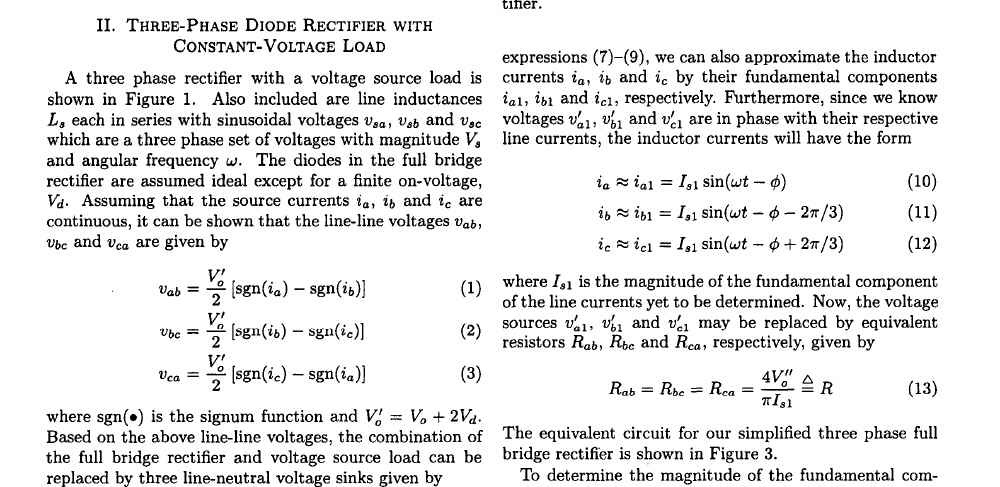 You will see that the phase to phase voltage waveforms are given by eq's 1,2,3. Sign um function can only take on 2 values +1 and -1. So each equation 1,2,3 can only have the values of V0' -V0' or 0. In contrast the currents are now sinusoidal as per equations 10,11,12. This is when there is NO ACTIVE REGULATION. Now look at the second set of plots. It clearly shows the SHUNT voltage going to zero when it should be either V0' or -V0'. It also shows the SERIES regulation voltage going to the V open loop AC sine wave when disconnected from the battery. The current also when to zero. QED | ||
Nightsky |
This paper you've linked has some problems. Stator voltage equations 1,2,3 that you've cut and pasted are approximations. They are grossly incorrect over some voltage ranges. Suppose Vo in Fig 1 was greater than vsa + vsb. The diodes would never switch on, and vab, vbc, and vca would be sine waves. There will be a transition to flat topped waves as the AC sources increase in voltage. But it won't be an sgn() function. That's probably why the authors have listed equations 7,8,9 and 10, 11, 12 as approximations. They're being sloppy and are too lazy to state the conditions in which the equations are approximately correct. The authors also assume an ideal voltage source for the load. Batteries have internal resistance and need to be protected by regulation against overvoltage. There are no humps in your yellow waveforms, just flat 14.0V, indicating there is regulation occurring. Batteries can be overdriven to 15, 16V or more otherwise. Are you saying the stator current is always low enough to not overdrive the battery beyond 14.0V without regulation? Notice that the paper does not mention regulation. This paper is about 3 phase rectifiers, and they are calculating current as a function of frequency and voltage so designers can know what rating rectifiers to use. They do not mention regulation. The paper models the battery as a 0 ohm ideal voltage source for all currents. In summary, the paper is invalid when discussing the measured waveforms because equations 1,2,3 only approximately model the stator voltage well enough to calculate average rectifier current. The equations do not have the fidelity required to discuss the stator waveforms. (Message edited by Nightsky on June 10, 2012) | ||
Posplayr |
The equTion accurately reflect the non regulating case where the diode bridge goes into conduction. That is the case shown in the first plot, That is certainly more plausible than suggesting that a shunt as well as series regulator is going into an intra cycle linear regulation mode at 13.0v when there is not any current even flowing to a battery. It is also pretty amazing how predisposed you Are to discOunt an IEEE publication? Regarless of weather there is any internal resistance in the battery, the model accurately reflects a fixed voltage load. In fact the referenced paper takes that as a standard result from a prior reference. Are you still challenging that? Are you sure that timebandit is not nightsky? It sounds like the same kind of illogical statement. | ||
Timebandit |
>Are you sure that timebandit is not nightsky? Paranoid? No, Nightsky isn't me. If there are any doubts about that, the admins/moderators have ways of confirming that. Part of the problem here is that you're grasping at straws, and searching for anything technical that you can find to back up a failing argument. You're trying to fool non-enginners by posting irrelevant information that obfuscates the issue in an effort to make you look smart. It's sort of a reverse ad hominem argument: Effectively you're telling people, "See, I understand this, so I must be right on that." The logic fails. Let's stick to analyzing your data. The truth is that the data that you've collected just isn't complete data, and your failure to collect all of the key pieces of data has caused you to misinterpret the data that you did collect. I think you would have reached an entirely different set of conclusions if you would have also monitored load (battery) voltage and battery current on your scope traces. To completely analyze the function of the regulator, it would be helpful to see the input and the output voltage and current wave forms at the regulator. But you only looked at the input side. You completely ignored the output side, which is what matters to the bike. If you had seen that the actual battery voltages were being regulated to ~14V during all those periods that the yellow (stator) voltages were being clamped at 14V, then it would have been obvious to you that regulation was indeed taking place. Unfortunately, you didn't even look at battery voltage, and the result is that you completely misinterpreted the data and concluded that there was no active regulation. Let's think about your assertion that the square waves represent periods of no active regulation: Do you really intend to stand by your assertion that there is no active regulation by either the Shindengen or Compufire products at 2000 RPM? If so, that means that both of these products are pieces of crap that won't charge the bike at idle or at 2000 RPM. If you are right and that were true, it would be a compelling reason NOT to buy them. You've also published data (in the first pdf) that shows scope tracings at 2000, 3000, 4000, 5000 and 6000 RPM. In repeating each of your tests at the different RPMs, the charts predominantly show square wave voltages that are clamped at 14V. In other words, the stator output stays at 14V regardless of RPM. If your criterion for interpretation is correct -- namely that the 14V square waves represent periods of non-regulation -- then you have to conclude that the Shindengen product never begins active regulation at any RPM. To conclude that would be utterly foolish. Do you actually mean to say that these voltage regulators fail to regulate all the way through the powerband? That's just nuts. The correct interpretation of the data is to say that current remains flowing at high rates (blue sine waves) on every chart, while the output voltage stays the same, as a 14 volt square wave (yellow trace). The obvious conclusion is that the voltage does not change as a function of RPM because it is being actively regulated. (Message edited by timebandit on June 10, 2012) | ||
Posplayr |
Nightsky said: >>Pos, I am sorry but your above >>explanations do not match the waveforms >>you give. >>This is not an issue with 3 phase vs. >>single phase. Your yellow waveform shows >>the stator being clamped to 0V, and not >>rising as a sine wave. The rectifier >>diodes may be off, but the regulator is >>clamping the stator to 0v to avoid >>current transients. With no clamping, >>the blue current waveform would be flat >>at 0 during this time, because no >>current would be flowing. But the blue >>stator current is non-zero and flowing >>because clamping is occurring!!! >>If the vreg were not clamping the stator >>above 14V, we would see a rounded top at >>the stator sine wave hump, not the flat >>yellow line clamped at 14V. >>A true series vreg would be allowing the >>stator voltage to rise while keeping the >>load voltage at 14V. In the post above Nightsky claims that both the SERIES and SHUNT regulators are SHUNTING current in the 1.5K RPM plots. The observation is that the line to line voltage is zero (as it would be with shunting) and there is sinusoidal current flow through the stator (also indistinguishable from SHUNT regulations). So the point is fair enough and shows a certain level of sophistication on the part of Nightsky to recognize that point. There is a valid question, why is the voltage going to zero and the current continuing to flow if it is NOT SHUNTING (i.e. shorting the leads). However Nightsky makes another more unusual observation, that because the part of the voltage trace that is at 14V does not follow a sine wave (as he would expect) then he infers that the regulator is "CLAMPING" the voltage. Nightsky concludes that we are not looking at pure SERIES regulation (he is correct both SERIES and SHUNT regulators are doing the same thing and neither is in regulation; you are only looking at rectification) However he is suggesting that the voltage tops are staying flat at 14 volts due to CLAMPING? So Nightsky suggests that SHUNT regulation and CLAMPING to 14V are one and the same and than both the FH012A and the Compufire are the same SHUNT regulators. With the conclusion that >>The Compufire vreg is clearly regulating >>in shunt mode in the above picture. One more time: Because the SERIES and SHUNT have the same wave forms, Nightsky concludes they are actually the same type of R/R as opposed to thinking that neither is in regulation and therefore they look the same. That is NOT LOGICAL. The only way to conclude that they are the SAME is to conclude that there is no way for the line to line voltage to be zero except in the case when there is SHUNT regulation. Any proof that the line to line voltage can be zero without regulation would invalidate Nightsky's conclusion. Point #1 CLAMPING to 14V as Nightsky describes is not SHUNT regulation. SHUNT regulation means you short the stator legs at which time you will always see zero volts on the yellow plot. This is fair enough. How can the voltage go to zero if it is not shorted? I will tried to answer that question.... POINT #2 The CLAMPING to 14 volts is something else that Nightsky claims is yet another unexplained type of SHUNT regulation. Night Sky is claiming by these statements that SHUNT regulators both SHORT the leads of the stator and somehow CLAMPS the peak voltage to +/-14 volts while NOT SHUNTING. This is peculiar as it is well know that what a SHUNT regulator does is simply to short leads when the sense output voltage is above the setpoint voltage (e.g. 14.25-14.5V). I'm starting to think this is just obfuscations on the part of Nightsky which is similar to what Bubba is doing. In the IEEE reference I posted , the conference paper presented the equations of a 3 phase inductive source being full wave rectified an loaded by a constant voltage source. This is intended to represent what happens when you connect the charging system to a battery as is clearly stated in the paper. The paper shows that the line to line voltage do go to zero during a portion of the cycle and go to a +/-V batt the rest of the time with NO REGULATION this is only from RECTIFICATION. The fact that the voltage can go to zero without regulation invalidates Nightsky's conclusion above about zero volts being a direct indication of SHUNT regulation. He has failed to acknowledge that but is continuing to obfuscate matters by claiming that the IEEE is lazy and that the paper does not apply despite the stated purpose that it is representing exactly what we are talking about here. Who is pulling whose leg here? | ||
Posplayr |
Hey BUBBA what are you worried about? I have answered the questions as asked until they have become irrational. Now I showed why they are irrational. Your only purpose (for what reason still remains unknown) seems to be to discredit SERIES regulation and the Compufire product specifically even though it is documented all over the web that it is working well on many applications. You seem to be very protective of the reputation of EBR as is clear from many of your prior posts. You are either very dense or being paid to act dense and are attempting to obfuscate the issues here. Sorry I'm off the clock now. | ||
Posplayr |
Reepicheep Care to elaborate? I don't get your point. Thanks | ||
Nightsky |
Pos: We are looking at the waveforms for nuances to determine what is going on in the vreg "black box." The IEEE paper's equations are approximate and are being used to calculate average rectifier current. I am wary of people using papers that are time consuming to read with the argument "Are you saying these IEEE guys aren't smart?" You seem very confident that you know what's in the Compufire vreg. And it appears you've at least looked at some very boring papers on 3 phase rectifiers. Do you work for Compufire? It might be possible to build a bang/bang regulator similar to how the old auto car alternators worked. But I don't see ramping in the yellow waves at high RPM. The other nagging problem I have is that you are not correctly calculating stator power. Your red curve relates to vreg+load power. I say relate because you are missing at least a 3/2 factor. Stator power calculations involve the stator no load voltage, and you are not using that. | ||
Timebandit |
No, you're wrong on that. I'm not trying to discredit SERIES regulation at all. What I am doing is telling both sides of the story -- something that representatives of marketing companies are not willing to do. The truth is that any regulation paradigm has it's strengths and weaknesses. On this forum, people are very familiar with the strengths and weaknesses of shunt regulation because of extensive experience with that type of product. In contrast, there is relatively little experience on this forum with the CF product. As a result, people have only the marketing claims to rely upon. That's not a good situation to be in. For an end user to make an intelligent, informed decision in the marketplace, they need to have all of the facts placed before them in a clear and understandable fashion. If anyone cares to look back at my first post in this thread, they'll see that I have made no effort to discredit series regulation. I never questioned whether it works as advertised. I only pointed out some of the drawbacks to series regulation, the discussion of which is being intentionally avoided by the people who are marketing the products. I did this so that end-users could hear both sides of the story and make an intelligent decision based on facts. | ||
Timebandit |
For the record, I am not employed by EBR and I do not receive money from them in any way. In fact the situation is quite the opposite, I send EBR lots of money to buy cool stuff for my bike. If you're trying to impeach my credibility by inferring that I work for EBR, that isn't going to work. An affiliation with EBR would only increase my credibility on this forum. It would not decrease it. In attempting to decrease my credibility by inferring that I have an affiliation with EBR, you are shooting yourself in the foot. | ||
Posplayr |
>>Pos: >>We are looking at the waveforms for nuances to determine what is going on in the vreg "black box." In your quest for "nuances" you seem to missing the obvious. According to your conjecture the FH012A has three totally different forms of regulation a.) SHUNTS a portion of the flattop waveform below 13V b.) CLAMPS the line to line voltage to a flat top waveform at all voltages c.) SHUNTS the flat tops at 14.5V at above 14V output The Compufire operates by does the same thing in a.) and b.) above but opens the winding instead of performing SHUNT c.) above. This is way more complicated than any know implementations of SHUNT regulators I have ever seen. >>The IEEE paper's equations are approximate and are being used to calculate average rectifier current. I am wary of people using papers that are time consuming to read with the argument "Are you saying these IEEE guys aren't smart?" I used the paper as an authoritative reference to prove the form of the source side waveforms of full wave rectification without REGULATION. The relevant part is only that part I highlighted. The actual purpose of the document is irrelevant only the reference to the well establish results referenced are relevant. I don't understand how you can claim that the document is incomplete (lazy authors)because it did not establish the bounds of the battery and source voltage limits for which the equations are valid, and now claim that it is too much to read? I have no issue skimming documents like this, and certainly think it is relevant to the conversation and short of setting up yet another experiment is conclusive. Clearly the equations are only valid in a situation where the diode bridge is conducting, clearly the source voltages have to exceed the fixed load voltage source else all diodes are reverse biased). It is very unclear how you would possibly conclude that the 1.5K RPM waveforms are anything else but pure rectification especially since all the evidence points directly to the fact that that is all it is? >>You seem very confident that you know what's in the Compufire vreg. And it appears you've at least looked at some very boring papers on 3 phase rectifiers. Do you work for Compufire? I have an MSECE/BSEE but I'm not a power engineer and neither do I work for Compufire. I am confident in the results because of: a.) the confirmation of the behavior as evidenced in the electrical measurements, b.) the direct observation of the thermal characteristics of both the R/R and my stator and my motorcycle as a result of using the Compufire. and c.) multiple conversations with expert power engineers about the exact plots. >>>It might be possible to build a bang/bang regulator similar to how the old auto car alternators worked. But I don't see ramping in the yellow waves at high RPM. I am not so inclined, but the obvious simple experiment is to take a connect a full wave rectifier/battery to the output of a stator and confirm that the leg to leg voltages and confirm the waveforms as predicted by the IEEE papers. Then you know there is no other hidden form of control. I will leave that as an excersize for the reader. >>The other nagging problem I have is that you are not correctly calculating stator power. Your red curve relates to vreg+load power. I say relate because you are missing at least a 3/2 factor. Stator power calculations involve the stator no load voltage, and you are not using that. I stated pretty clearly to Bubba that it is simply a built in SCOPE function which only computes sum, difference, multiplication and division. That is all you get. It is what it is the product of the voltage and current traces. Caveats were noted. 3 phase power factors are worrying you? Do you actually thing that a scale factor error is going to change the shape of the curves? Even if there was a scale factor error it would have no impact to the issue of SERIES v.s. SHUNT regulation. | ||
Posplayr |
Bubba: Sorry for that "implied"accusation, I guess you are just dense. (Message edited by posplayr on June 10, 2012) | ||
Timebandit |
My name is not Bubba. Be aware that it's not a good idea to proceed with personal attacks, name-calling, etc., as that kind of activity can get anyone banned. It also lowers your credibility when you have to resort to personal slurs. It's probably not a good idea to continue with name-calling and attempts personal insults. Probably better if we all focus on interpreting your data in an objective method, avoiding getting emotional and confrontational. Confronting one another on the data and what it means is fair game. Making it personal is not. I'm going to try harder to keep things professional, and I'd appreciate it if you would do the same. | ||
Nightsky |
Pos: Your plots are labeled representing stator power. But you calculate vreg+load power. Your plots are invalid because they do not show what the labeling purports. Stator power calculations must involve no load stator voltage output. You are not doing this. Scaling is a minor issue. | ||
Posplayr |
Nightsky In you profile you claim to be an EE. So think about this: For the ideal case as shown in the subject paper, when there is a forward biased diode or closed MOSFET of the full wave rectifier, any individual leg of the stator is effectively tied to the fixed voltage of the voltage source load through the effective voltage drop of those respective devices. In other words when any particular leg of the stator has a forward conducting path in the rectifier, that leg voltage will be constant as long as the voltage source (load) is constant. So what is it that will change the load voltage. There is a well establish Thevenin equivalent model for a battery which is an ideal voltage source with series resistance. The only thing that would cause a change to the battery voltage is the charging current operating through the battery internal resistance. However at this RPM there is virtually no charging current and the battery is fully changed with low internal resistance. Therefore the only thing that can be expected is that when conducting you will see the flat top of the battery voltage with 1/2 of whatever forward drop is in the rectifier. There is no Sine wave voltage when connected to a voltage source, and when connected to a battery that is not charging , an ideal voltage source is basically all you have. That is why the tops are flat. | ||
Timebandit |
Nightsky wrote: Interestingly, PoS seems to know quite a bit about what is inside of the competing product from Cycle Electric. He's repeatedly told us what kind of components cycle electric uses inside of their regulator, while telling us that Compufire uses better parts and makes a superior product: PoS wrote: http://www.badweatherbikers.com/cgibin/discus/show .cgi?tpc=290431&post=2229057#POST2229057
PoS wrote:
PoS wrote: http://www.badweatherbikers.com/cgibin/discus/show .cgi?tpc=290431&post=2229057#POST2229057
Nightsky asks an interesting question in posing whether PoS works for �someone� in the industry. PoS certainly professes to know a lot about what types of electronics are inside of the CycleElectric product, doesn't he? How many bikers are going to take apart a perfectly good CycleElectric voltage regulator to obtain that kind of information? I wouldn't even do that, and I took apart a dead Ducati regulator! The only people with incentive to do that are CycleElectric's competition; the electronics manufacturers routinely disassemble their competitors products to see what's inside. Bearing in mind that PoS has been promoting the Compufire products pretty hard, saying they're the best thing available, and that he's been discrediting the CycleElectric products based upon their �inferior� electronic components, I have to agree that Nightsky poses a valid question in asking whether PoS works for Compufire. I may have been totally off-base in thinking that he was shilling for Motoman. | ||
Timebandit |
Nightsky wrote:
Regardless of whether or not the device might function using bang-bang regulation, PoS has failed to make that claim � in fact, he specifically claims that the Compufire product works differently. So I wouldn't worry too much about a bang-bang regulator hiding in that box. If there is a bang-bang regulator in there, then it's NOT the series regulator that he claims it to be. Nightsky wrote: First, we have to agree that those red traces on the drawings are total BS. They do not come directly from actual measurements, they come from him telling his PC to fabricate the red trace by multiplying the yellow trace by the blue trace. The red line was not generated by any valid objective measurement. The red plots are invalid in estimating power in any three phase system because they are based solely upon measurement of one single-phase lead. You're right, if he were trying to calculate anything meaningful, he would have had to have applied a correction factor of 1.5 to make any inferences about three phase power. But he didn't do that. As a result, his representation is false. It's important to note that the 3/2 correction factor for assessing power in three phase systems is nothing new � it has already been discussed in this forum. I share Nighsky's nagging concerns about PoS being asked to provide solid definitions at the beginning of this discussion, and then dodging the issue by either providing low-quality non-engineering responses, or providing no responses at all. As an example, before this discussion got going, Nightsky asked PoS to provide an operational definition of Shunt Regulation and Series Regulation. Unfortunately, the definition of Series regulation that PoS provided was just awful. It was so vague and inaccurate that it referred to a �series� regulator as being something that was �in series with the load.� PoS wrote: http://www.badweatherbikers.com/cgibin/discus/show .cgi?tpc=290431&post=2229351#POST2229351
According to such a poor definition that is based on topology and not electrical behavior, any shunt regulator would qualify as a series regulator under the PoS definition because it's black box physically lies in series between the stator and the battery, with one end connected to the stator and the other end connected to the battery. What Nightsky asked for, and what PoS didn't provide, was an ELECTRICAL definition of the different regulation paradigms. PoS avoided giving a precise, accurate answer. As a result in proceeding with this discussion in the absense of a concrete operational definition for series and shunt regulation, we now have bickering and hand-waving about whether or not shunt regulation or series regulation is taking place. In many respects, this discussion is proceeding as if the apple cart is in front of the horse. A concise, accurate operational definition needs to be agreed upon before we can continue. Until that happens, people are going to resort to hand-waving and quoting arcane articles that have nothing to do with the topic at hand, but seem to be on-topic enough to confuse readers who don't know any better. A better approach would be to agree upon concrete terms that define exactly what a shunt regulator is, exactly what it isn't, and exactly what a series regulator is, and exactly what a series regulator isn't. These definitions should include the types of waveforms that each type of regulation should produce when oscilloscope leads are attached to the charging system at different locations. In doing that, it will be possible to unequivocally use the oscilloscope criteria to define regulator behavior and regulator type. Until that happens, proceeding with petty arguments is fruitless. Without a concrete set of rules, we're reduced to "he said, she said" arguments like PoS is offering now. How about we lay down some concrete rules that will allow us to use PoS own data to PROVE who is right and who is wrong, and that we limit our analysis to looking at the oscilloscope tracings that PoS has posted for the two regulators, instead of continually trying to pull-in outside references? We have yet another problem -- Nightsky has pointed out that the question of exactly how to calculate power dissipation in the stator is something that PoS has been working very hard to avoid answering. I have asked him directly how to calculate stator power, and he has refused to provide any firm answer. Instead, he responded that "sometimes" the red traces indicate power in the stator: PoS wrote: http://www.badweatherbikers.com/cgibin/discus/show .cgi?tpc=290431&post=2229168#POST2229168
Once we have a set of rules to guide us, I'm going to prove that the red traces in the data that PoS has collected NEVER indicates EITHER power delivered to the load OR power dissipation in the stator. PoS really needs to go on the record about how he calculates three phase power delivery to the load and the power dissipation in the stator, because the hallmark of shunt regulation involves dissipating incredible amounts of power in the stator, and the claims of series regulation is that it does not. Once he gives us the answer about how power dissipation is calculated, we can go through the PoS own experimental data for both regulators, and demonstrate for the reader how much power dissipation each regulator puts onto the stator. The results are going to be very interesting to read, and will open up many peoples' eyes about the claims that are made by these aftermarket products. PoS, I'm asking to you put your reputation as an engineer on the line and provide precise definitions on the following topics: 1. How to accurately define series regulation. Your �it lies in series with the load� answer was wrong, and grossly inadequate. 2. How to identify shunt regulation using an oscilloscope. 3. How to identify series regulation using an oscilloscope. 4. How to calculate power dissipation in the stator. 5. How to calculate three phase power delivery to the load. You've been asked these questions several times, and you continue to avoid answering them. You'll to a lot to protect your reputation by answering the questions now. Once you've done that, we'll have the foundation laid for proceeding with this discussion. If you continue not to answer these questions accurately, I consider that a forfeit on your part because you just don't know the answers. | ||
Posplayr |
Hey Bubba: Have Nightsky come back and answer the perplexing questions I asked him. Or is he in dispose" at the moment? Both of you should have figured out how the measurements were taken and what all three plots are unless you think they are fabricated? Nightsky questions what source side waveforms from 3 phase rectification looks like when driving a battery? Stick to that first. You have challenged me technically with a barrage of questions. I have answered everything from Nightsky but he has not answered the nagging questions about his conclusions. I will not play along with your obfuscation of the fundamentals; have him answer to the incongruence of his logic. | ||
Timebandit |
I can't speak for Nighsky. Like I said before, I'm not him. I'm sorry, but I can't control him to suit you. I asked you not to continue with the name-calling and I agreed to be civil in the hopes that we could address the outstanding questions in a constructive fashion. I don't understand why you're persisting with the name calling. I guess you're just frustrated. It reflects poorly on you. I'm hoping that we can establish some common ground on what the proper definitions are going to be in interpreting your sample data. In the spirit of fairness and cooperation, I am giving you the chance to participate equally in defining the standards by which your experimental data set will be interpreted. This is your big chance to help define the rules by which the game will be played. Put your engineering reputation on the line and provide succinct, clear, and comprehensive definitions on how to interpret the data. If you opt to waive the opportunity to participate in establishing the proper definitions, then you are giving us consent to define the standards by which your data will be analyzed, without your input. I guarantee that if you don't provide any input, the results that will follow will not be to your liking. This is your last chance to have input on the rules that will be used to analyze your data. If you decide not to participate, we'll provide the standards by which your data will be judged. This is your last chance to have input. Don't blow it. |