| Author | Message | ||
Timebandit |
AVC, we should really pursue this stuff in a new thread. this hijacking has gotten out of hand. I would like to know what GAUGE the wire from the buss bar to the RR is in the factory harness. -- Avc8130 That's a really good question. What you're really asking is whether or not Buell properly revised the charging system harness for 2009. I've already told you that I don't know the wire gauge off of the top of my head, and that someone is going to have to go look it up. I don't really understand why you keep asking me for the answer. Someone has to look it up. You can look it up as easily as I can, and since you're the one who wants to know the answer, I nominate you to do the lookup.  Once you've looked it up, please report back to let us all know what you find. Once you've looked it up, please report back to let us all know what you find. If it is, it should be ~8 Gauge. If it isn't...an upgrade to the wiring harness there would be benficial. Wire gauge selection for ampacity is a not only a function of current. It's a function of current and run length. You can use smaller gauge wires over short runs than you would have to use over a long run. The answer to this kind of question is best expressed graphically, but it's easiest to find the answer in the wire ampacity tables that you'll find in the appendix of any EE handbook. If I had to place a blind-faith bet on this, I'd bet that Buell engineering got it right. The only other qualm I have is where can a user hook up accessories in the buss bar... the textbook answer to that question is that you create a new accessory circuit off of the bussbar (not the battery post!), with proper gauge wire, and a properly sized fuse. the analogy to the home distribution panel is that you just go to the bussbar, plug in the proper sized circuit breaker, and pull appropriately sized wires for the new circuit. That's what I would do. I wouldn't go daisy-chaining onto any of the existing circuits. in other words, how much juice is "missing" when 1/3 of the stator is shut off? that leg-switching business really screws things up, doesn't it? i know the answer, but i'm not going to open the can of worms relating to how many coils really get deactivated when you interrupt one stator leg. i've fought all the uphill teaching battles that i care to fight. conventional wisdom says the answer is 1/3. i recommend going back to the schematic diagram for the stator, cutting one leg, and tracing coil circuits to see how many coils still have 2 intact wires to allow current flow. the answer would surprise most people. (Message edited by timebandit on January 12, 2012) | ||
Avc8130 |
I realize I can go look at the bike for wire size, but I figured you might have your hands under the seat before I do since it seems you are actively pursuing this stuff. Me? I'm trying to sell the bike. LOL I am aware that wire length as well as free-air versus confined space can lead to what size wire is "proper" for a particular current in a particular situation. I am just working from past experience where increasing the gauge of certain wires has resulted in better light output and higher charging voltages. Assuming Buell got it right is like assuming they changed anything else when they went from the 08 to the 09 setup. Just looking at the 09 charging system has me eternally skeptical when it comes to Buell engineering. Manufacturers have a lot of variables and the final design is always a compromise. Available connectors, total cost, weight, etc can all result in a setup that might not perform optimally with regards to charging/power output because it sacrifices to save weight/cost/etc. Logic says 1/3...what is the truth? EE is something that has always intrigued me but I just never had enough time to devote an entire course of study. PS: How's the pooch? ac (Message edited by avc8130 on January 12, 2012) | ||
Timebandit |
Logic says 1/3...what is the truth? that's a knee-jerk answer that you get when you just count how many legs have been cut. knee-jerk logic isn't the right way to get the answer. you have to draw the schematic and count functioning coil circuits. it's easy to do. somebody needs to do that and give the answer... not me this time around. | ||
Avc8130 |
12 pole stator? How many wraps on each pole? Each leg makes a wrap, skips 2 poles, makes a wrap, repeat? ac | ||
Timebandit |
don't make it more complicated than it has to be. just think about 3-phase stators in schematic form.  | ||
Avc8130 |
Unless I am nuts, or just totally lost (most likely) I'm starting to think we have 1/2 the charging capacity with 1 leg removed. Brain fart...thought about it more. 2/3. It's amazing that is enough juice to run the bike...oh wait...it's not...and we run off the battery. Guess we are back to that 30A circuit. LOL ac (Message edited by avc8130 on January 12, 2012) | ||
Avc8130 |
Let me actually ask for clarification. Is the 1125 Delta or Wye? LOL 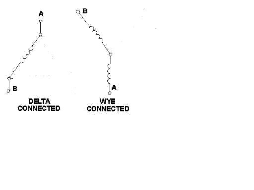 ac (Message edited by avc8130 on January 12, 2012) | ||
Timebandit |
in general, delta produces more current but at a lower voltage, than a wye, which produces less current but at a higher voltage. we want amps not volts, so i would spec a delta design for the stators. i can't say for certain which one buell uses, as i haven't looked at one up close. when a three phase transmission line loses one leg, the power engineering types call that condition "single-phasing" because the three phase circuit loses two phases when you interrupt one wire. that's a really dangerous situation for 3-phase motors, but we're talking about a generator here. in a standard delta, the three circuit paths are AB, BC, and AC. in your diagram for the delta, you removed the connection at "C". that eliminates all flow through leg C. that means that BC and AC both get taken out, and only circuit path AB is left, as you showed in the diagram. similarly, with the wye configuration, single-phasing takes you down to one circuit path. AC and BC are interrupted and only AB remains intact. the result is that interrupting ONE leg with the relay interrupts TWO legs of the stator. everyone who has always thought that it interrupts ONE leg hasn't thought the problem through to the extent that you just did. of course, this is a bit of a simplification. when a 3-phase circuit is damaged and single-phasing results, you do develop ghost voltages in the severed legs. then the math gets complicated. i won't address that here. the result is that 1/3 of the stator gets used for power, and the other 2/3 gets used as a heat sink. power loss is significant. this is why you don't want to spend all your time riding in the dead-zone. lug around at 2500 RPM and you'll start threads asking people why your batteries don't work.  | ||
Timebandit |
loss of one leg in a three phase system: http://www.youtube.com/watch?v=yy3hKtuY9Bg | ||
Avc8130 |
Time, Thanks for walking me to the water. No more thirst here. I think those 2 schematics and your words should explain it clearly to just about anyone. Those 3 posts should be a sticky. ac | ||
Yugi |
I was trying to tell the same in another thread, that when one leg is cut, you're losing 2, but nobody believed me. | ||
Avc8130 |
Yugi, I think the schematic Time posted, and the modified one I posted make the point quite clear. File them away for the next time it comes up. ac | ||
Froggy |
Thats what did it for me, it made it easier to understand. Timebandit, Avc, thank you for this discussion, I learned quite a bit  | ||
Avc8130 |
Froggy, Is there anyway to get a sticky for just that information? Maybe include the parameters Time posted in another post for HOW the ECM controls the harness too? ac | ||
Timebandit |
Sometimes a graph helps. This one is just a sketch to illustrate the principle. Numbers were not taken from actual measurements. 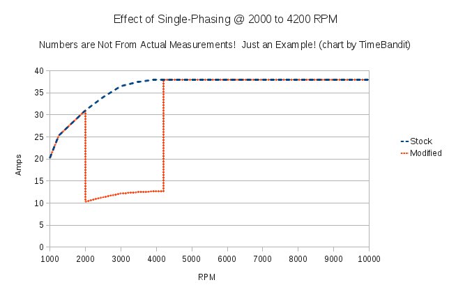 This graph shows that when the relay is activated between 2000 and 4200 RPM, charging current is dramatically decreased. | ||
Dannybuell |
I am in way over my head here. Are we discussing the harness relay with the line graph? | ||
Avc8130 |
Yes. Note: line graph not to scale. ac | ||
Timebandit |
AVC, the blue line is not "to scale", in that I didn't go out and actually take new measurements off of a 2009 charging system to draw the chart. What I actually did was to take real data that I already had from a 2008 system, and scale it up by 25%, since the 2009 system has roughly 25% more output than the 2008 system. I think that's a reasonable approximation -- good enough for teaching purposes, anyway. The Blue line is pretty much how I would expect the real 2009 chart to look if someone actually took real world measurements off of a 2009 system. I made the disclaimer to warn everyone that there could be a discrepancy between this diagram and the real world data because I wanted to be honest that I didn't actually take a fresh set of measurements off of a 2009 system to prepare the chart. Danny, the blue line is the expected baseline current output for a "stock" 2009 charging system that doesn't have the Product Program #0507 Harness Upgrade. The numbers are representative of how I think the real 2009 curve might actually look. The orange line *IS* to scale with respect to the blue line. That is to say that it was generated by multiplying the predicted blue line output by 33%. The orange curve decreases to 1/3 of the blue curve's value when operating in the Single-Phasing region of the graph. The orange curve really is THAT BAD in the Single-Phasing (relay-switched) region. You end up with about 1/3 of normal output, because you're throwing away 2/3 stator output when you need it the most. (Message edited by timebandit on January 14, 2012) | ||
Avc8130 |
Time, Safe to say it the relay induced comma on the charging system isn't TERRIBLE unless you maintain the bike in that zone for an extended period of time. 30A current can be drawn from the battery during this time period. I don't know how many amp-hour the stock battery is, but I wouldn't purposely keep the bike South of 4500rpm for an extended period of time and then immediately shut it down and expect it to restart... ac | ||
Dannybuell |
THX :-) | ||
Zac4mac |
OEM battery is a 12 AH AGM lead-acid battery. I won't argue Time's graph, I didn't think the alternator put out 200+ Volts-Peak-to-Peak. I put a scope on it and it was 200 V P-P at ~5k rpm... Thanks for the teaching, Time/Bob. Z | ||
Avc8130 |
Zac, With that info, if a user needed the entire ORIGINAL charging system output and desired to ride around between 2000 and 4500 rpm, that person could do so for approximately 36 minutes before the battery was toast. There are probably a few variables there...but it is an approximation. ac | ||
Timebandit |
Zac, no problemo. I've learned a lot about my bike from very helpful people on the forum and I'm just trying to give something back. | ||
Timebandit |
Safe to say it, the relay induced coma on the charging system isn't TERRIBLE unless you maintain the bike in that zone for an extended period of time. That's the take home point. The bike produces a reasonable amount of charging current at idle. About 20A. And it increases to full output of ~38A by the time you're at 4000 RPM. This means that in the unmodified configuration, the charging system produces enough power to run the bike and a pretty decent accessory load without any problems. The high output 2009 stator really is doing it's job well. The only problem that you have is heat generation that's caused by inadequate cooling of the charging system. Heat is your enemy. Keep in mind that to the designer of a race bike, low RPM is equivalent to low speed. Transfer of heat in the engine is dependent on oil and coolant flow. Both are dependent upon RPM. At low RPM, the bike isn't circulating much oil/coolant, and at low RPM/low speed there's not much air flow across the cooling system. Under low RPM conditions the bike is not capable of removing much heat from the stator. All the heat is trapped by the stator cover because the stator doesn't have adequate oiling. The stator sits in a hot box. That cooks the stator. Somebody at H-D came up with a solution that was actually pretty clever. They've defined the low-RPM state as a low-speed, low-cooling state. To them, that is the danger zone. You don't want to generate lots of heat at low speeds where you can't use the cooling system to get rid of it. So they use the ECM to single-phase the charging system to avoid heat production at low RPM. Once you're going 4500+ RPM you've got decent air and oil flow to cool the bike, so they bring the heat generation of the charging system back online. I think that the people who have argued that the charging system update is bad are people who don't quite fully understand how it's designed to help them. Other things to consider: * You want the rotor oiling upgrade. * Revving at a stoplight hurts you. It actually decreases charging system output. * If you're idling, you still get all the unwanted heat, but you also get the full charging output from the system when you need it most. You don't want to drain the battery while idling and risk not being able to restart the bike. * If you're worried about avoiding heat production, ride the bike below 5000 RPM. * If you're worried about having adequate cooling, run the bike above 5000 RPM. * To minimize heat production and maximize cooling, maybe you could run low RPM at high speed by choosing the "wrong" gears. * Someone whose riding style traps them in the pit is going to punish their battery without mercy. It'll always be in a discharge state, it will always be generating sulphates, and when a battery has a hard life like that, it tends to have a short lifespan. Being nice to it at night by putting it on a tender might not undo the damage that comes from riding around all day in the dead zone. * If you like to ride the bike at low RPM then it may be possible to ward off stator failures by sacrificing batteries. | ||
Dannybuell |
I bypassed my harness last year. I ride in the dead zone 99% of the time. My seat of pants feeling is that ignitions like the extra current at those speeds. I like the battery staying alive without a tender. The rotor oiler is a must do for everyone. | ||
Shags |
So Yougi do you think you can make the connectors.The one for the positive and negative side of the rr to the factory connector to the bus bar,if co i would gladly take one of each.Great work and thanks. | ||
Avc8130 |
Danny, Do you have the rotor oil mod? ac | ||
Yugi |
I don't have the connectors from the VR to the harness, and I don't know where to get them. I can make the cables from the stator to the VR. So far people here are interested in ordering 6 cables: Rkc00 - 1 Froggy - 2 Ros - 2 Shags - 1 I can make them, as soon as I get the parts. I can provide my paypal address, if everybody is agreed. So that will be $25 per cable. I think shipping will not exceed $5 So far, I installed the regulator today and made a test ride for about 50 miles. It was holding good so far. The voltage stood at 14-14.4 when riding, 12.7-13V when at idle, with heated grips on and both fans running Without the grips it was around 13.5V when idling. I removed the charging harness for now, but I may reinstall it back later. Regarding the temperature, I feel that the stator cover is still pretty hot, but I think not as hot as before. The regulator gets hot, when idling, but pretty cool otherwise. | ||
Dannybuell |
No but it is very encouraging and on my list of things to do when the time comes.. | ||
Ros |
I don't have the connectors from the VR to the harness, and I don't know where to get them. I can make the cables from the stator to the VR. So far people here are interested in ordering 6 cables: Rkc00 - 1 Froggy - 2 Ros - 2 Shags - 1 I can make them, as soon as I get the parts. I can provide my paypal address, if everybody is agreed. So that will be $25 per cable. I think shipping will not exceed $5 Yugi I'm waiting for answer of my friend, so I cannot assure if I want 1 or 2... And are you aware that I'm from Spain? I say due to inexpensive shipment costs. Thanks |