| Author | Message | ||
Rodrob |
After a lot of digging, I have ben told that the O2 sensor inputs on the 1125r ECM are actually 10bitADCs, which means that they will accept the 0-5 Volt output of a Wide Band O2 controller, not just the stock narrow band sensors. Apparently this means that accurate AFR values can be logged directly out of the ECU serial (diag) connector by the appropriate software, and that AFR values will be in sync with all the other ECU data for, I hope, accurate tuning. Note that this will only work with race ECUs or other "tunes" where the O2 sensors are ignored, as the ECU is programed to only deal with narrow band sensors. I have ordered Wide Band Sensors and will report the results of my tests. I would not try this until I can verify the results. Do this at your own risk. | ||
Qwik59 |
Hmm I'm interested, keep us posted. | ||
D_adams |
Hmmm, never tried hooking up the wideband inputs to the ecm instead of the narrowband. I think on mine it's just a matter of moving the wire to another plug. I might have to try this. | ||
Rodrob |
I have confirmation from additional sources that this works. I have yet to receive my LC-1 Wide Band O2 sensors. Be aware that if you hook up the wide band output, your closed loop values will be way off. I suggest you turn that off first if you have the capability. | ||
Easyrider |
don't forget to reset the wideband sensors on regular basis (-: I keep an eye on the results | ||
Aseecobra |
Rob, Concerning your statement of the race ECM ignoring 02 inputs, both of my pump gas race ECMs from Erik Buell Racing are in closed loop using the narrow band sensors below 5K rpm. Chris (Message edited by aseecobra on May 13, 2011) | ||
Rodrob |
Yeah your not the first that has mentioned that. So I will check mine as well. My statement was based on input from Erik Buell Racing when I was installing my race harness and discovered only one O2 sensor connections. I was told to not be concerned as the O2 sensors are ignored on the race ECM. But it appears that is not always the case. Thanks for the input. | ||
Rodrob |
It works. I now have wide band LC-1 O2 sensors connected to the ECM and am able to log the data from the diag connector using Tuner Pro RT. Now I need to figure out how to apply this data to the fuel map. Any guidance would be appreciated. | ||
Rodrob |
Well I finally read V2 of the buell tuning guide thoroughly. I wish I had done so before I started all this. I had read V1, but V2 is a lot more comprehensive. It clearly states that you can log WB O2 data with the ECM (Douh!). I also states that the LC-1 sensors that I bought do not have enough output current to drive the low impedance input of the ECM correctly (ARRGHHH!). Ill do some tests today to confirm. There is a master Closed Loop Enable flag in the ECM, that does not seem to be working as expected. Anybody have any info on this? | ||
S21125r |
Rob, Been a while since I tinkered with Tuner Pro, but last year I set up a translation table so that all of my 02 values(standard O2...) translated to a -1,0,+1 (lean, stoich,rich). From there I could pass that value to History/Running Average tables. Not very useful for me other than showing I did have some lean/stoich spot where I was expecting to be full rich. For you, you could either average the raw output from the WB in the history tables and then manually calculate AFR, or could probably set up a similar translation table to convert to AFR first before passing to the history tables for averaging. Let me do some memory jogging and see if I can pass some ideas your way. | ||
Rodrob |
Thanks so much for the response. I was able to use a conversion formula in a New ADX Value named "O2-Front AFR", to calculate AFR from the O21 ADC output. Rm+((RM-Rm)/ADCM)*ADCV Where: Rm is the minimum AFR that your WB sensor reads. In my case 7:1 or 7 RM is the maximum AFR from the sensor. In my case 22:1 or 22 ADCM is the maximum number the O21 ADC will resolve. 255 for 8 bits ADCV is the current value of the O21 ADC Point the "O2-Front AFR" Value to source the same address as O21 ADC This makes X in the conversion expression = ADCV so using my setup the expression would be: X*((22-7)/255)+7 And it seems to work fine. BUT... The O2 ADC (rear cylinder) outputs a number in excess of 255 which makes no sense for a 8bit ADC, so I don't know what value to use. Do you have any clue as to what is up with O2 ADC? | ||
S21125r |
Rod/b, Don't have much for you other than I noticed that O2 ADC is 10bit while O21 ADC is 8bit. So suspect you need a different conversion factor. 8 bit represents a number between 0 - 255 and I think 10 bit represents a number between 0 - 1024. Don't quote me on that though :-) You may try substituting 255 in your equation with 1024 and see if that fixes it. | ||
S21125r |
Rod/b, I sent you a PM on this yesterday with some instructions, but instead of creating a new "value" and addressing it to same address as 02 ADC and 021ADC, you can modify each of those existing parameters and send the raw data to a Lookup table instead. Look up table (for 8 bit to AFR) would be like: 0 = 7 17 = 8 34 = 9 ... .. . 255 = 22 Then when you run it through the History Tables it will calculate based the translated AFR value instead of the raw 8 bit/10 bit value. Your way works, just offering a different way to skin the cat. | ||
Rodrob |
Awesome. 10 bit output makes perfect sense. Max decimal is 1023 inc. 0. Would also explain why O2 Source is 16 bit LSB first. I'll plug this in and give it a try. Alternatively, the formula: V*(RM-Rm)+Rm Where: V is ADC converted to Voltage RM is Ratio Maximum Rm is Ratio minimum Will give you th AFR form a Voltage. Using the conversion factors from the O21 and O2 DX Values, the expressions in my case would be: X*O2 Factor*(22-7)+7 X*O21 Factor*(22-7)+7 This seems to work as well. Thanks for the feedback and help. Any idea why I can't seem to disable the Closed Loop Function in the ECM? I've tried setting both ) O2 Test Min RPM & O2 Test Min TP to maximum but it does not seem to work. Every time I plug in the WB sensors, things go haywire. Sorry for all the question but I'm trying to get the bike setup to tune at the track this weekend. | ||
D_adams |
I disabled mine last year by setting the closed loop range at 100 to 500 rpm or so. It never runs there, so it never learns. | ||
Rodrob |
So I got everything installed and working. The AFR calculation works with a little tweaking due to a slight voltage drop at the LC-1 output when connected to the ECM. The motor still gets a little haywire when the WBs are connected, especially at idle. There is a Enable Closed Loop at Idle flag set, but un-setting it does not seem to do anything. I think there are parameters in the ECU that are not implemented in firmware. I am told by Xopti that resetting voltage parameters to accommodate WB voltages does not work for closed loop operation. Too bad. I was hoping it would. Still not sure how to use the data. I'll play with some History Tables tonight to see what I can come up with. As always, any input is appreciated. | ||
Rodrob |
Here is a screen grab of the logged data playing back. 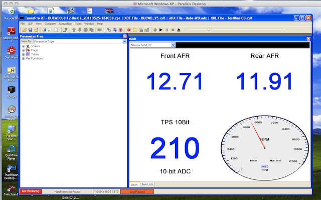 I'm running on a Macbook Air BTW | ||
S21125r |
Good stuff Rob! I love experiments like this not necessarily for the destination, but for the journey :-) The History tables are your friend. My personal suggestions for using them are: - Bump your sample count up a pinch, maybe 25 - 50 samples. - limit the number of variables that the engine has to compensate for. i.e. don't log during warm up, pick a day to log where ambient temps and baro pressures are pretty stable, etc. No stop and go where coolant temps and battery volts are all over the board. Focus your logging in the conditions and area of the map that you are concerned about. - Reference the sample count for each cell after logging to make sure you have a fair number of samples to form an opinion on. 1 or 2 samples would be like trying to approximate the total US population based on the population density of NYC. - Reference the standard deviation too. small deviation means that most of your samples are tightly packed around the average. Large deviation means they are scattered all over the place and pretty much inconclusive. After that I think it's going to be subjective. What AFR your at, vs what AFR you want to be at, and how many point to add to the fuel table to get there. You might even find that what you think should be a good AFR for a particular range of cell actually make the bike feel flat in those areas. Good luck and keep me posted. | ||
Rodrob |
Since i's my race bike, I will be doing the logging on the track, assuming I can get my computer mounted securely. Looking at the fuel tables, do you know what parameter is represented by the 8 bit value of the row labels? I assumed they would be Throttle Position, but it's a 10 bit value. (Message edited by Rodrob on May 27, 2011) | ||
S21125r |
Rob, From the looks of it, the fuel tables are using a vertical axis of Load 8 bit. But there is a table in there (TP to Load Table) that equates Load 8 bit to TPS 8 bit. So for all intents and purpose vertical column is TPS 8 bit. History Tables seem to use TPS 8 bit directly so should still be a "apples to apples" view between fuel map and history table. | ||
Rodrob |
Thanks! After much frustration trying to get the WB sensors to work on the NB inputs, I have learned that there are AUX 10bit ADCs in the ECU that should be used for the WBs. I have yet to discover where the data for these ADCs show up in the stream, but I will be working on that this week. This should means that you can log WB and NB simultaneously, if your sensors can output both. This should give a very accurate picture of what fuel the ECU sees it's getting, and what the motor is actually getting. | ||
D_adams |
Mine will put out both, but where do you hook the WB into the ecm? No manual handy (it's at home, I'm at work) so I guess I'll have to hunt for it later. Haven't really looked at this much yet, just downloaded tunerproRT the other day and got it installed on the netbook. I have a bit to learn yet. Need to figure out which xdf/bin/whatever to use. I have a lot of them, but don't know which one matches what I have at this point. So much to do, so little time. Almost caught up on building pipes, so maybe I'll catch a break where I can do some of this. | ||
S21125r |
If you have the v2 Buell Tuning Guide handy, do a search for AF1 ADC and AF ADC. Both are 10 bit so looks promising anyway. Label show them as "Air Fuel Sensors" yet there are different ADCs for O2 sensors. My .adx file has them already added, so it may be more of challenge to figure out how they should be connected to the ECM and if you start seeing data pass through those two ADC. | ||
Rodrob |
Ok, I got it working.The AUX ADC inputs are on pin 1 and pin 33 of the Grey ECU connector. I'm told that you can get pre terminated wires from the dealers, but I cannibalized a torn up harness. Connect the WB sensors to those inputs. The data from the ADCs will show up at offset 0X6D and 0X6A. In TunerPro RT, these addresses have Values defined as AFR1 and AFR2 in the latest Buell ADX file. Locate those values in the ADX and in the conversion tab set the following expression formula: X*0.019607843*(RM-Rm)+Rm RM is the Maximum AFR range of your sensors at 5 volts Rm is the minimum AFR range at 0 volts. That will get you very close. To compensate for small voltage loss due to ECU input impedance, Add the loss in volts to the X*0.019607843 product. So: (X*0.019607843+.V)*(RM-Rm)+Rm The LC-1s have serial digital output and logging software, so I calibrated the analog voltage into the ECU against that. Make a dashboard that has three gauges. One points to AFR1, one to AFR2 and one to TPS ADC. Use /4 in that expression to convert 10bit to 8bit. Now you should see WB AFRs and Throttle Position in real time. | ||
S21125r |
Nice find on pin 33 - guessing you had a "birdie" tell you where to look? I figured you'd find one on pin 1 based the info I saw on the spy website but I didn't find anything for the second ADC needed. You going to tune via real time dash readout or use history tables/logging? At any rate, keep us posted - I like self discovery projects like this even if I don't intend to make any changes. | ||
Bueller4ever |
Is the front cylinder always more lean than the rear? The AFV #'s I've seen don't reflect it. What were your AFV# during that log? I'm referring to Rodrobs picture. | ||
Easyrider |
Bueller4ever, The front is always in the riding wind, and cooling more. Cold cylinders use more fuel then hot cylinders (-: | ||
Rodrob |
My AFVs are at 100. However the EGO values are constantly changing. I plan on using history tables/logging for tuning, but I am still unsure as to the best way to do that. Suggestions/input is, as always, appreciated. Yes, I have had many birdies. Thanks to all of them. | ||
S21125r |
Shoot me a copy of your log file (xdl) and your log def (adx). Shouldn't take more than a few minutes to whip up a history table for you. BTW - I noticed on many of my standard logs that I get weird "glitches" that pass through the data stream. By glitches I mean every few minutes I'll get a single sample where almost every sensor reading goes out of scale. Bike will be idling yet it records a glitch sample past red line @ 0 TPS. Other inputs like map flake out like this as well. I haven't looked hard enough yet, but assuming there is a way to filter those out. | ||
Rodrob |
Thanks! Will do. |