| Author | Message | ||
Curve_carver |
I'm taking a leap in fate with the FH012AA mosfet style regulator. I just ordered the kit and will report when I get her hooked up. I usually ride at least 12k a year if not more. Specs are 50 amp at 14.5 volts. http://cgi.ebay.com/ebaymotors/ws/eBayISAPI.dll?ViewItem&item=380299088748&viewitem=&sspagename Pretty impressive. IxE=P 725 watts WOW Instruction are in this thread. http://www.badweatherbikers.com/buell/messages/290 431/592310.html?1283454984 I have some time so I'll play with locations. (Message edited by Curve_carver on March 01, 2011) | ||
Froggy |
Cool, let us know how it works for you!  | ||
Dirty_john |
I fitted an FH12AA from a Yam R1 after another forum member did a great job and posted his ideas, it works well and has huge spare capacity. I mounted the unit under the pillion seat as shown by Blk09 (I think) and made some cooling air slots in the rear seat undertray. (Message edited by Dirty_john on March 02, 2011) | ||
Fast1075 |
It is impossible to overstate how important cooling for the regulator is. The waste energy is converted to heat and dissipated by the regulator. If it doesn't cool well enough it will fry. It is that simple. If the VR fries and goes open (on any or all legs), voltage runs wild and stuff burns up from overvoltage. Heat sink and airflow are your friends..Go check out an XB and see where the regulator lives..(they work exactly the same way...as do many other motorcycles). Ages ago when I worked at Honda, we had a sizeable number of regulator failures in spite of their heavy cooling fins....fixed the problem by moving the regulator to a cooler location. | ||
Rob_l |
Yes cooling. If the reg. is dissipating heat to the frame then why does the reg. only contact the mounting plate at the fasteners with most of the surface not touching the plate. All the heat transfer compound in world won't help that reg. cool. I asked the dealer about the gap when they put on #2 reg. and they said they checked other 1125's and they are all the same. | ||
1_mike |
Funny...this is one reason my CR's stock regulator has a high flow computer, power supply type fan blowing air across it.. Mike | ||
Crowley |
After no end of reg/rect problems on my VTR track bike, I fitted a R1/R6 reg/rect to that bike, along with heat compound and a big far cough ally plate. End of problems there too. 'Tis a common mod on Ducatis with an underseat reg/rect too. | ||
Reepicheep |
Kinda. Kinda not. A shunt regulator can be built like the Buell stock regulator is, meaning that it is an open switch or a closed switch. When an open switch, the voltage is up to 14.5 volts, but the current through the switch is zero. So power dissipated by the regulator is zero. So say 14.5 volts times 0 amps is zero watts. When a closed switch, the voltage is zero, but the current is huge. So say 0 volts times 50 amps, still zero watts. Those are theoretical maximums you can't achieve though, the forward drop of the SCR with the Harley VR means it can never go below 1.2 volts or something. And the "on off" switch is not instant, so there is power spent there as well. So the regulator is actually using the stator as a huge part of the overall heat dissipation... probably like 80% of it at the end of the day. Which makes sense. I haven't done the math, but I bet 500 watts would be enough power to turn 5 pounds of aluminum molten in just a few minutes. A small soldering iron is 15 watts, a halogen worklight is 300 watts. Imagine 500 watts concentrated in an area the size of a voltage regulator... (Note the logic above only works for a shunt regulator. A series regulator has different problems and different equations). | ||
Rob_l |
Ah, remember the old Triumph's with the sunburst rectifier right out front, now that's cooling. | ||
Dirty_john |
FH12AA shuts down on overheat according to the OEM literature, but yes cooling is critical to all components in the charging system (Message edited by Dirty_john on March 02, 2011) | ||
Fast1075 |
The amount of electrical potential is determined by the stator physical properties, the strenght of the magnetic field in the rotor and the speed of rotation... Some of the electrical output is used directly by the ignition, fuel and managment systems as well as the lighting and accessories...with the voltage high enough to charge the battery...the natural balance point comes at a particular rpm depending on load....above the break even point, the excess current has to the "disposed of"...the route needed is one or another form of resistance...hence my statement that it is dissipated as heat. This is true and common with any fixed field system...provided there is a requirement that the system must charge within desired parameters over a widely varying range of engine speed... The fixed field system is used in applications where simplicity and cost are the primary factors. | ||
Reepicheep |
Agreed Fast, and nice description. I was just clarifying that most of the heat is probably put out of the actual stator windings. It'd be interesting to measure how much and what percentage. My Uly is charging the battery at idle with all accessories running (including heated grips). So the break even point is somewhere below there. | ||
Sparky |
Mike, a fan sounds like a good solution. I've put my fingertip on the VR heat sink at times and nearly got burned. Do you have a picture of where the fan is mounted? (Message edited by Sparky on March 02, 2011) | ||
Curve_carver |
Well, I know what I'll be doing this weekend. I'll take some good pictures on my mounting. Id like to mount it in the same location if I can. 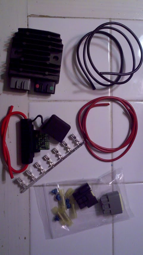   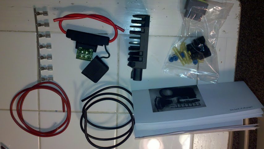 | ||
Curve_carver |
Anyone check their stator resistance lately. Does anyone know what it should read on a DMM or have the spec? | ||
Curve_carver |
 | ||
Nuts4mc |
Don't know if this will help Mr. Curve... this is a FH014 I had to make connections and "pot" the wires with silicon gasket maker (RTV) 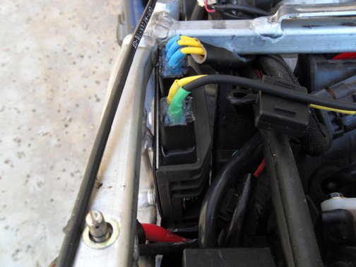 | ||
Nuts4mc |
here is mount details 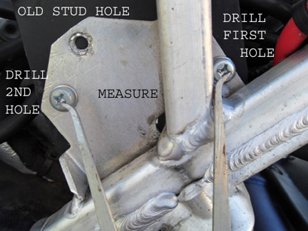 | ||
Nuts4mc |
overall view 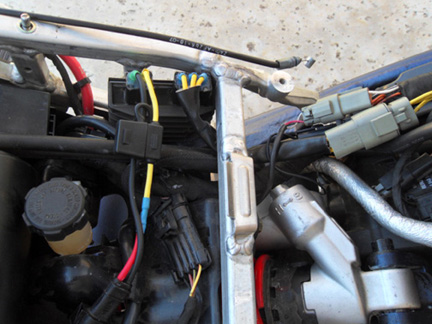 | ||
Curve_carver |
This is what gave me an indication to replace the regulator. I also noticed it was charging low when hot and high when cold(12v when hot and 15.2 when cold) Look at the blackish yellow wires. The flash on the camera lightened the wires up. They were darker than what the picture shows. Notice only two where black. Ya gotta love the relay setup. LOL  First I removed the regulator. Then I used the sharp chisel and chipped the tack welds off the original mounting plate and removed it.   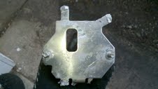 It's very important for the stock regulator make contact to original mounting plate. It was the only way it could cool. The new mosfet has cooling fins which ultimately has better heat dissipation. I also removed this bracket which would increase air flow over the new mosfet. Here is a shot with the plate off and the tack welds knocked off. I used a file and ground down all weld splatter and old tacks. I wanted to have a flat even surface when mounting the new one. In the picture where my finger is you will notice where I removed a little plastic in the pan. It was 1" long by 3/4" wide. I wanted the regulator to sit low for clearance against the seat pan, other wiring and gas vapor lines. 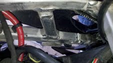  Now I was looking at where she would fit best.  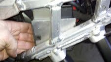 I forgot to take pictures of my next step but I'll explain it as best as I can. I cut some 1.5" wide aluminum strap to the regulator's length and drilled it to the new mounting pattern. This piece will be sandwiched between the regulator and subframe.   I left my wires long just in case I have to change something. I used the 50 amp fuse which added a ton of wire but I just want to be safe for now. I am running all three phases and disposed the relay harness harley put on the bike. It was snowing so I only had it running at idle. The readings were 14.5 with hid lights on and both fans running. The lowest I seen was 14.3 . When the rain and snow clears up I'll take her for a spin.  (Message edited by Curve_carver on March 06, 2011) | ||
Curve_carver |
Finished product. It could be cleaner but I'm happy with it overall. I'll wait and see if it works before I clean it up.  | ||
Sparky |
Kudos for a good job and out-of-the-box thinking but, IMHO, you mounted it backwards to where the cool ambient air is - the open duct in the body panel. You have the fins facing inward where hot air from the engine goes.  Perhaps the position of it can be reversed by turning it around and mounting with standoffs? | ||
Curve_carver |
No worries I'm happy with it where its at. Remember this regulator is rated at 775 watts at 50 amps. Its a little oversized id say. Lol I took in consideration when I mounted it that I don't get stuck in traffic. There's always airflow moving through the duct. That's another reason why I removed the plate that blocked the duct. I ran it at idle for 30 minutes and it wasn't even warm. I think it'll be okay. | ||
Gemini |
looks great. nice attention to detail and clean installation. was there room to mount the regulator with the connectors pointing towards the ground? my only fear would be with a connector pointing straight up, it would be more prone to gathering water inside the connector that any other direction. keep us posted | ||
Jules |
Great job. My only observation would be that you have introduced two variables into the change - the new VR and the removal of the sub harness. The removal of the subharness could also explain higher charging voltages. It's not a criticism, I understand your reasons for doing the two changes and TBH I hope this works out. It'll be very interesting to see how you get on over the next few thousand miles.. | ||
Jules |
OK - like a lot of people i've been reading a LOT about the stator/Regulator/Rctifier issues not just on the 1125 but also on the Aprilla, Triumphs, BMW GS, Suzuki SV/DL and TBH quite a few bikes that seem to have identical issues to ours. It's a real struggle to find any "definitive" answer, lots of other people have installed the MOSFET R/R and most seem "content" but TBH they're generally fxing an issue with either poor connections or the R/R itself. The cheap shunt R/R fitted to many bikes (ours included) obviously just shunts the current to earth and generates a lot of heat in the R/R and because the Stator is always providing full power that also has heat dissipation issues. Although this MOSFET R/R does run cooler it doesn't actually seem to do anything to help the Stator run cooler, how could it? The Stator will still be providing its full output and therefor still creating the same heat. The Series R/R seems to be the only way to regulate the actual output of the stator and therefor allow it to run cooler. The crossfire R/R seems to be the product that does this... I realise this is a sales pitch but I found this document quite interesting: http://www.posplayr.100megsfree3.com/FH012AA_Charg ing/RR_Tutorial.pdf I still have my fingers crossed that the FH012AA MOSFET R/R may do something to help, but I'm a little less sure now than I was before..... I think I'd be more inclined to go the Compu-Fire route... | ||
Curve_carver |
I have a few suspicions what is wrong with this whole 09-10 charging system but I have no proof to back it up. I did notice that my yellow wires were turning brownish black as I indicated in the pictures above. Thats why I attacked the regulator first. The regulator was on its way out and charging all over the place. We'll see how long this setup lasts then and if it doesnt last I'll will have it rewound or buy a 08 rotor and stator. From the look of my stock regulator I had to buy a regulator anyways. I like being a test dummy. | ||
Jules |
LOL - I'll definately be keeping an eye out for how that setup works out... I like others to "pioneer" the way, then sneak in and steal all the good ideas :-) | ||
Curve_carver |
looks great. nice attention to detail and clean installation. was there room to mount the regulator with the connectors pointing towards the ground? my only fear would be with a connector pointing straight up, it would be more prone to gathering water inside the connector that any other direction. keep us posted I thought about putting some silicone on the top. I'll think about it. | ||
Hootowl |
Aren't those connectors weatherproof already? |