| Author | Message | ||
Pso |
I recently had my voltage regulator go out and had it replaced under warrenty several weeks ago. I have a GPS that plugs into the cig. lighter on the dash. The gps shows the voltage. I noticed today that the voltage was hovering around 12.6 or.8 at between 3 and 4K. On the first VR the voltage was in the upper 13's and would hit 14v at times, so were the reading from the new VR, until today. What could be causing this? Is this a sign that the stator is going? Is the new VR starting to crap out? Or do I need a new battery? Any ideas suggesions or tips on how to diagnose the problem (If it is a problem) is greatly appreciated. I also pluged in my radar detector that has a volt read out on it and got the same readings as the gps. I also made sure the bolts to the battery are secure. | ||
Froggy |
Sounds normal to me. The 14 Volts means the VR isnt VR'ing propperly. You fixed it and now are in the 12V range.  | ||
Florida_lime |
Normal running at rpm should be 13.8 - 14.3 volts for most vehicles, with an at rest condition of 12.3 - 12.8. Of course I haven't checked mine to see what it reads at 3-4000 rpm, but I would think higher than what you are getting now.  | ||
Gamdh |
Happen to have checked mine last week .. in the 3-4k range is was 14.2-14.4 (used 2 different voltmeters, so 2 slightly different readings) | ||
Lost_in_ohio |
Just did a tps reset tonight and was watching the voltages. 900rpm 12.5 volts 1k rpm 13.4 volts 1.8k 14.1 volts. just and observation while I had the bike hooked up to the laptop. I thought someone might find it interesting. | ||
Froggy |
0.o hmm i guess im the one with the charging issues then, i will have to look into that. Too much crap bolted on it. | ||
Xbimmer |
Check your 77-connector... at 4k the VR should be shunting like crazy to keep the volts to the battery limited to 14+/-. | ||
Hughlysses |
Check your 77-connector... at 4k the VR should be shunting like crazy to keep the volts to the battery limited to 14+/-. +1 for the 77-connector. Mine recently almost stranded me- a VERY subtle burn mark on one of the metal tabs in the connector was preventing the battery from being charged at all. (Message edited by Hughlysses on August 07, 2008) | ||
Rays |
If you haven't seen this document I put together it might help you. This is the second version and there have been quite a few folk on Badweb who have used this procedure to their advantage - some have given good feedback, others haven't -  http://docs.google.com/View?revision=_latest&docid =d4rbxwr_20dq5khf&hl=en | ||
Pso |
Like florida lime and Gundh, when bike was new and also after the VR swap, I was getting those readings of high 13 low 14v's. I will check the #77 connector. When the VR had failed several weeks ago, I went to Annapolis Hardley and asked them to make sure to check that connector. They told me the connector looked good. When I came back several days later to get the bike after they swapped out the VR the service manager told me that it seemed as if the connector had been arcing. He said that the tech said it may be due to the aftermarket driving lights I have mounted. Duh, they told me the connector was ok just a few days ago. He went into bovine stare mode. Anyway I was thinking about doing away with the phillips connector by connecting the wires together with different methods listed on this site, but I was not sure how to differentiate the wires if I needed to replace the VR again in the future. Evidently there are two black wires in the phillips connector, so the first time I do it I will be able to determine which black wire from the VR to connect to which black wire on the other side, however if I get a new vr I am not sure how I wil know which black goes to which because the phillips connector on the bike side will no longer be there. Any ideas recommendations? I have some of those nuts that someone else on this site has used. Rays, thanks I have printed out your doc and will follow your worksheet tonight. | ||
Thunderbox |
It is normal to have a lower voltage if the battery is not very well charged. As the battery charge comes up so should the voltage. If the voltage doesn't improve then I would say you either have a bad battery or a bummer for a VR. Either way the first part that should be tested when you have a charging problem is the battery, then the output of the alternator should be tested. Thats as long as all the connections are clean and secure. yes you should have a charging voltage reading of 13.8 to 14.3 with a fully charged battery at 3000 RPM. | ||
Pso |
Thunderbox- When battery is connected on bike and I turn on bike and not start it I get 12.0v on both the GPS and also Radar Detector. Would this be an indication that the battery is good? I did this little test shortly after I had run the bike at hiway speeds. | ||
Pso |
Sitting in a boring meeting today I realized I have a spare VR that I purchased as a result of my last failure. Perhaps I will just connect it and see what happens to the voltage. I do not believe that I need to do anything other than plug the cables from the vr into the two connectors. I will insure that the connector on the bike is a good fit as was pointed out in Rays article, thus if my voltage goes back up to 13/14V I will know it is either the connectors or the vr I have on the bike. Any cautions I should be aware of with this little test? I am hoping that it works and thus perhaps I will just swap out the vrs and use the one on the bike now as the limp home spare if need be. I also remember reading somwhere back about someone putting a zip tie on the #77 connector to keep the internal connections tight. anyone able to stear me to that little gem of wisdom? | ||
Xbimmer |
...but I was not sure how to differentiate the wires if I needed to replace the VR again in the future. Very good point. I used a piece of white tape to match the red to the battery and black to the VR. Found this today, this is how I'm fixing mine: 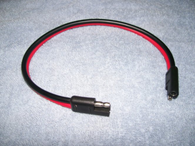 Haven't been able to find one in 10 gauge until today. What do you electronics wizards think? | ||
Reepicheep |
10 gauge (not counting the connectors) is rated for 55 amps for chassis use. So you could be on the edge, but you are pretty close. It would probably work. The connectors may be an issue, they may be able to carry less current then the wire. They clearly have less volume... | ||
Hughlysses |
They clearly have less volume... Holy crap- there has to be 10X the metal-to-metal contact area in that plug compared to the stock plug. If that plug is inadequate, the stock plug must be WOEFULLY inadequate. | ||
Reepicheep |
My concern was not the surface to surface contact, it was the "donut" of material that will be carrying current between where the female connector has crimped the wire, and where the male connector starts making contact. Thats going to be a much lower volume of conductor for that short segment. Of course, current capacity is really a measure of ability to dissipate heat, and its a little section with big heat sinks on either side of it, so it will probably be fine. Ultimately you can probably assume that if they stuffed 10 gauge wire on the connector, they probably also found a connector that is rated for about the same amount. That kind of assumption hardly ever leads to things catching on fire.  | ||
Hughlysses |
Bill- I can see what you're saying now. At any rate, there has to be significantly more minimum cross-section in that connector than the stock one. At least with my connector, the problem was in the lack of good contact between the male and female halves of the connector. Any ideas for a connector that would provide more positive engagement between the two halves? | ||
Pso |
I think that I found the problem. Seems like when the VR was replaced the tech that buttoned the bike back up pinched the orange and white wire from the other connector next to #77. I used electrical tape around the exposed section and got a voltage reading of 13.9 at 4k rpm. I am going to get some liqued tape and fix those wires a little more securly. Xbimmer good idea on marking the two black wires coming from the VR. I am thinking of useing #8 split bolt connectors and shrink tubing to replace the #77 connector. But the other connectors being explored on this thread is also very interesting. | ||
Thunderbox |
Hey Pso. Glad you found the fault. In answer to your question a fully charged battery should read about 12.3 or 12.4 volts. A reading of 12V indicated that the charging system was no working properly which you already know. The battery would be about half charged. | ||
Darthane |
Go measure the width of the blade on the male terminal in the 77 connector and let me know what it is. I can tell you exactly what the ampacity is per a given ambient temp, and the rise above ambient given the current running through it. It's a Delphi connector, and I'm sitting in Delphi's Dearborn Customer Service Center at the moment with a stack of product information books in my overhead.  ...I'm pretty sure it's a 6.3mm blade, which is rated for up to 55A depending on the ambient. At 50C it's like 46A continuous. What's the output on the stator? (Message edited by darthane on August 08, 2008) | ||
Hughlysses |
6.3mm = ~0.25 inch. I don't think there's any way the blades are that wide. Mine's not handy to measure, but based on what I saw, I'd say they're much closer to 0.125 inches = 3.175 mm. I was really surprised they were so small. My guess is the ampacity is much, much less based on that? (Message edited by Hughlysses on August 08, 2008) | ||
Darthane |
If they aren't 630s, then they're 480s (4.8mm width). No way in hell would they use a 280 for that application (won't accept 10GA wire), and the connector's too big for it in any event. The ampacity of a 480 is about 42A at 50C, and about 50 closer to freezing. I suppose I could go pop the cover off my Uly...I might just have to do that at lunch - now my curiosity's peaked. I've had that connection apart on my Firebolt when I replaced the stator, but aside from inspecting the terminals for signs of arcing or spreading, I don't recall just how big they were. Oh, and food for thought - the interface between the two terminals is not necessarily the weak point in terms of ampacity across the connection. The quality of the crimp and the thickness of the terminal stock likely have a bigger impact (providing the interface is connecting properly). (Message edited by darthane on August 08, 2008) | ||
Reepicheep |
If I was going to cobble it (and I would have by now if I had a problem, but I haven't), I would probably get something as big as I can crimp on there, and bolt them together. Its probably fine though... run it with a low battery and both headlights on and see if it gets all melty | ||
Red_chili |
Darthane, seems like you might have the short path to success for us depending on what you find over lunch? It would be nice to get ordering information for an upgraded connector. Not wild about the split bolt idea, though I am certain it works fine. | ||
Darthane |
Grr...I forgot I Loctited all those freaking screws a couple weeks ago. I'm going to need something more than the little T27 in the toolkit to get it off. I'll take a quick peek when I get home before I run off to dinner and see what size it is. If it's a 480, I can probably get my hands on a similar connection pair, but 630-series instead. ...or, for those unlucky enough to have melted one, I might be able to dig up replacements. There are even larger ones (800-950 series), but really, that's major overkill. The stator is only rated at 30A. Problems that people have had with the connector overheating are due to the connection being loose, which causes arcing and heating of the terminals - not due to the terminals being inadequate for the job. | ||
Red_chili |
A cut sheet describing crimping procedures, cautions, inspection criteria, whatever, etc. might be cool too, if you have one. Thanks! | ||
Darthane |
Hmm...so I get home, take care of a few things and then go back out to the garage to take the pulley cover off... ...and discover that there IS NO connector 77 on a 2008 XB12XT. O_o I traced the wires from the VR back and sure enough, they route on the left side of the bike, past the starter and down into the primary case. If there's a connector buried in there I'd be surprised, but that means the VR is directly connected to the stator. I'm not willing to crack my primary open just to check on this, but I am intrigued. I pulled the cover off of my Firebolt, and it is indeed a 480-series connection. I'm going on vacation for a week, but if someone would be kind enough to remind me I'll be happy to see if I can secure a small supply of the connectors, terminals, seals, and some 10GA wire. I can try to find a 630-series replacement, but honestly, the 480-series terminals are more than capable of handling a Uly's stator output. Red, crimping the terminals onto the wires isn't a big deal, but most people have only dealt with the 'quick-crimp' style, where you simply crush a ring down onto the exposed copper. 'Real' terminals have two sets of wings, one of which curls down into the copper core and another of which wraps around the insulation/cable seal. To crimp them properly you need a multi-sized crimp tool. They're available at NAPA for like $25 or so (or at least they were when I bought mine 9 years ago). For any hand crimps, you should always solder them when you're done, which will virtually erase any errors in the crimp due to not using a specific die stamp for it. ...it sounds a lot more complicated than it is. If I can get hold of the right terminals/connectors/seals I'd be happy to just crimp lengths of 10GA wire to them and then anyone that needed to replace the connector need only splice the wires together. | ||
Hughlysses |
Darthane- there has got to be a break in those wires somewhere. There'd be no way to get the stator installed in the primary & the wires routed out of the primary to the voltage regulator otherwise. The connector IS buried on an 07 Uly behind the front sprocket cover and at least 2 other connectors. | ||
Froggy |
The 08's use a totally different stator, infact half the stuff related to the engine is new for 08. That is why there is no 77 connector. I am sure there is a new version of it, just somewhere else with a better connector. |