| Author | Message | ||
Timebandit |
You're dead wrong. Opening one leg in a three phase power system single-phases the output. That's one of the basic principles that is taught in a 3-phase power course. That's idle speculation your part. It's a pretty strong accusation to make, saying that the guys at BMC/HD who developed the harness update never paid any attention to stator currents. There's no engineer in his right mind that would fail to hook up an ammeter when addressing this problem. Consider this: if hooking up an ammeter was something so obvious that it occurred to you, why should anyone think that it wouldn't be just as obvious to someone who actually understands how a 3-phase power system actually works? You've spent a lot of time on this forum bad-mouthing the Buell design. You've said that that Erik and the guys at EBR were incompetent, and you continue to proclaim that their fixes are incompetent hack-jobs. This makes me wonder why you're even here. Well, obviously you're not here because you like Buell bikes. You're here because you're trying to promote Compufire. I think you're missing a very important point -- Bad-mouthing Erik and his engineers doesn't raise your stature on this forum -- it lowers it. | ||
Posplayr |
Bubba, Lets see; someone designs a modification that puts a mechanical relay in series with a high current stator device. The relays keep burning up...........hummmmm "Oh but trust me I know what I'm doing. A $900 rotor is what you really need." Oh and by the way you should be real happy to get a replacement stator for $1000 from the factory. Just beware of anybody that won't rewind a failing part of a defective system for free. Biased????? | ||
Timebandit |
Get your facts straight: 1125 Rotors don't cost $900. 1125 Stators don't cost $1000. The rotor fix costs $175. | ||
Timebandit |
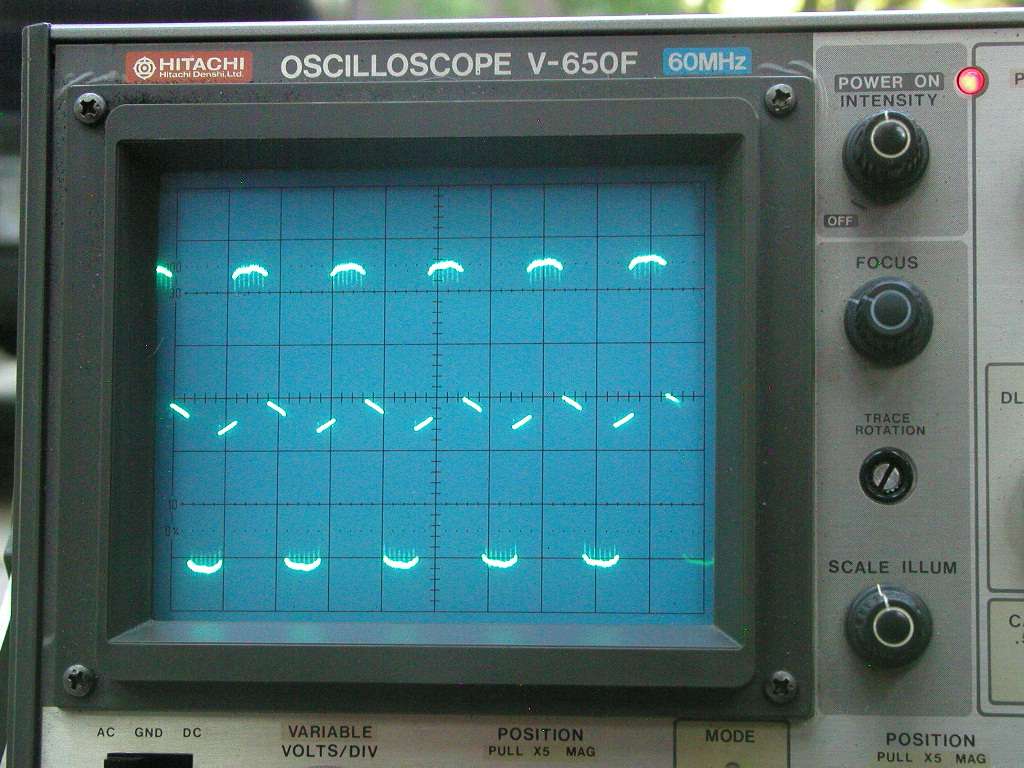
What Real Data Looks Like: I dragged my garage scope out into the driveway today and took some scope shots of a stock 2009 Buell 1125R charging system in action. My bike has the OEM 2009 stator/rotor, the Ducati shunt regulator, and the charging harness update. The following photos were taken using a vintage dual-trace 60 MHz Hitachi analog oscilloscope. I used differential lead placement across two stator leads to provide common mode rejection. In other words, I placed two probes (Channels A and B) on two stator leads, inverted the input for channel two, and performed an A-B summation. Probe grounds were attached to directly the negative battery terminal. Scope settings were 5 volts/division, 2 msec/division. Here is the trace to confirm probe calibration. Notice that both Channel A (top) and Channel B (bottom) are tracing perfect square waves. (For the calibration photo a 0.5V reference standard square wave was used, and the scope's vertical amplifier was set to 0.5 V/division.) 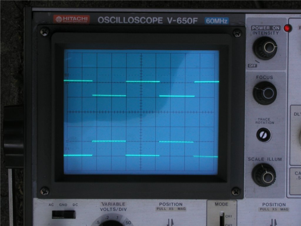 (more to follow) | ||
Timebandit |
In this photo the mode switch was flipped to "Sum A+B" with the B-inversion button engaged. Notice that the two calibration waves sum to produce a flat line. This scope is properly calibrated. 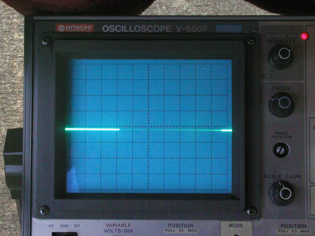 (more to follow) | ||
Timebandit |
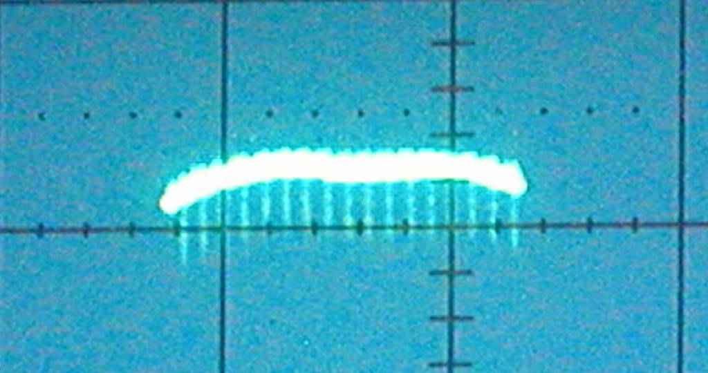
All of the following scope photographs are taken with the scope set to 5V/div and 2msec/div. The throttle was varied from idle to about 3000 RPM as snapshots were taken. 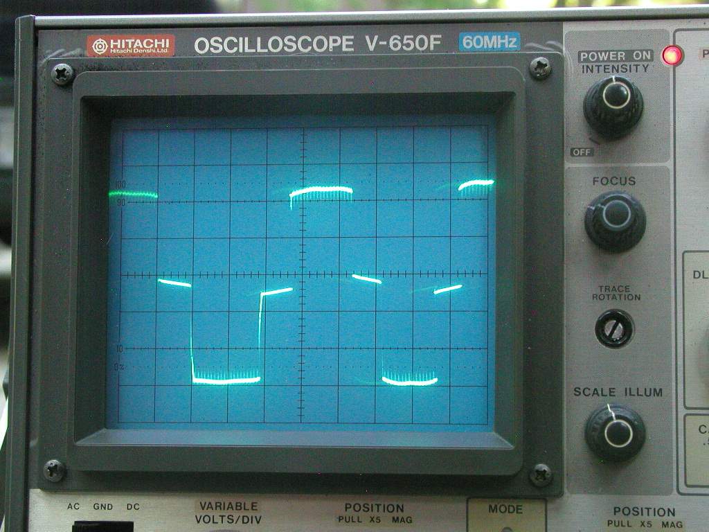 | ||
Timebandit |
 (more to follow) | ||
Timebandit |
 (more to follow) | ||
Timebandit |
 (more to follow) | ||
Timebandit |
 (more...) | ||
Timebandit |
 (more...) | ||
Timebandit |
 These photos have been jpg compressed (harshly, I might add) to make them small enough to host on the BW site. If anyone is interested in the full resolution photos I'll post them to photobucket. | ||
Nightsky |
That's exactly how I instrumented my scope. Dual channel differential A-B between two legs of stator. Ground leads from both probes clipped together to one longer wire back to battery ground. This provides best frequency response and highest common mode rejection. Simply clipping scope ground to one stator leg and using single channel is not the way to go. That makes the whole scope frame go up and down with that stator leg. Timebandit, you should be a photographer. I want to hang those shots in my living room. | ||
Nightsky |
Posplr, the relay harness really cuts out 2 windings externally. By disconnecting one stator leg, the charging system goes from 3 phase to single phase. The relay harness cannot stress the remaining winding more than normal operation. The ducati shunt vreg limits battery voltage by shunting across the stator. Less charging because only 1 winding is active means lower battery voltage and less vreg shunting. It's less stressful on the stator to dump into 14V than a dead short. So the relay harness helps the remaining winding. | ||
Timebandit |
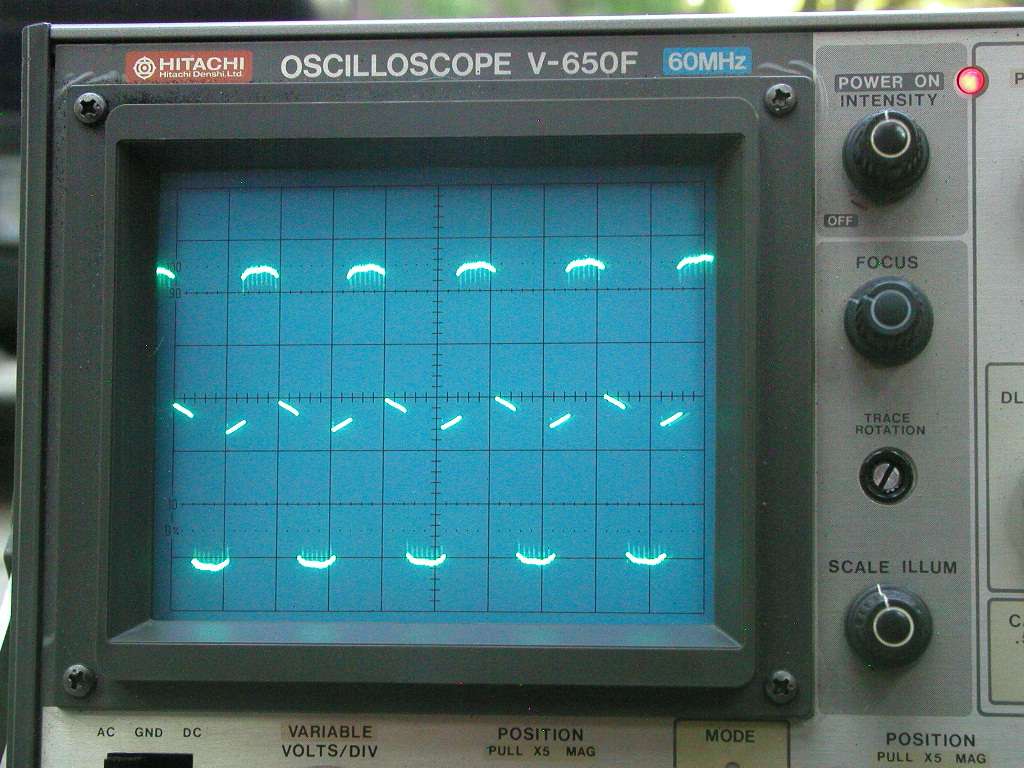
I used a 10-year old digital camera that's on it's last legs. The key is to use shutter priority, and set the shutter speed to equal the sweep period for the scope. That way you don't get ugly double traces. Waiting for a day with good diffused indirect daylight also helps a lot. Proper instrumentation of the scope is essential. If you don't properly instrument the scope, then you'll have high common mode noise, poor frequency response, and you'll produce charts that are noisy and fail to document the high frequency switching that's going on during the battery charge period. It's no surprise to me that when someone fails to properly instrument a scope, they fail to see key pieces of data that are in the signal. If your scope setup can't resolve the "jellyfish" then your data is crap and you end up drawing the wrong conclusions. Yep, these traces conclusively demonstrate that there is indeed regulator activity going on during the battery charging period, that in the real world the charging period is never a flat topped square wave, and that the 0-volt baselines are never quite flat in a real 3-phase stator. Of course, if you model/dry-lab your data using an over-simplified model, then everything will be nice and flat.  I'm particularly happy that the photos came out so well to demonstrate the high frequency spikes (regulator activity) that overlay the charging interval. I can see them in your photos, but the out-of-focus blur makes them a little hard to appreciate for someone who doesn't know exactly what to be looking for. I wanted to get a set of nice, clearly focused images to prove the point that you were making. The reason that we can see the "jellyfish" while other's cannot is because we did proper differential sampling to ensure a low noise floor and high frequency response. Hooking up a probe to one stator leg and the ground to the other isn't the way an expert would collect data. In general, experts want to use differential sampling to avoid noisy data and compromised frequency response. Worst of all, you want to avoid having a scope with a floating chassis potential on the order of 50 to 120 VAC while you're doing the tests!!! Yikes! You definitely don't want that! Instrumenting a series regulator becomes particularly dangerous when the series regulator goes open-circuit and the stator is unloaded. Depending on RPM, you could be dealing with voltages from 50 to 120 VAC, and 40 amps of current. That's enough to *KILL* someone who isn't careful. You definitely don't want to work with a hot-chassis scope and those kinds of voltages. Grounding the scope to a stator lead is a really *BAD* idea. (Message edited by timebandit on June 20, 2012) | ||
Posplayr |
Nightsky, I saw some of the ongoing debate about what happens when you open one leg of the stator (I assume you are not opening two legs). And yes I understand opening one leg will make a Y wound stator go from 3 phase to 1 phase. However you are still going from 3 windings down to 2 windings so no matter how you look at it there are still two winding creating the output power so theoretically you would be dropping down to 66% power. However the current in the stator is only there because it is being supported by the magnetic flux in the rotor. The magnetic saturation is what ultimately limits the current in the stator, else the power would keep going up to the square of the RPM which it does not. So if you are in a saturated region (on my Suzuki it is at about 3000 RPM) and you try and drop the stator current by opening a leg it might not drop by the full 33%. Anything less than the full 33% would correspond to an increase in current to the two remaining legs. Somebody needs to get an AC current clamp and actually measure how much current there is in the stator. If there is a stator relay employed, measuring the actual leg current with the open leg would probably be illuminating. Pos | ||
Posplayr |
Nightsky, Well it appears as if this Ducatti R/R is yet another animal to the other three R/R's I posted. It would be useful to see what the current is doing, but it appears to be a SHUNT Switcher of some sort. The FH012A and the Honda both change SHUNT duty cycle synchronously with the AC. The Compufire seems to open the legs synchronously. This Duccati, seems to be free running chopping the AC. I wonder if it still has a full diode bridge? With a measurement of the output voltage you could tell how much voltage it is dropping when conducting to the battery. Diodes would be dropping 0.7-0.8V . The MOSFET and the CF both do synchronous rectification where they time the AC voltage waveform and switch the FET's to rectify (negating the need for a diode bridge with the associated losses). When it is shorting (the low voltage sections), it doesn't appear to be a hard short in which case it would be disappating alot of power in the R/R. Pos | ||
Kinder |
Didn't read through all this... Just wanted to say I'm running an 08 retrofit stator and the compufire VR. Riding home volts read into the 16's and then cluster shut down showing system voltage thing. If I pulled in the clutch and dropped the throttle to lower th rpms it would come back on then off as soon as I got n it, Just saying... Going to go back to stock. | ||
Posplayr |
Kinder: Are you running with a Relay harness modification as well? If you are really getting 16V then the Compufire is at least partially toast. Should never do that. | ||
Kinder |
No harness. 08 stator on for less than 400 km | ||
Nightsky |
Pos, These stators are delta, not wye. Disconnecting one leg gives you one winding in parallel with the other two in series. Disconnecting one leg only allows current to be drawn 1/3 of the time as before. Flux arguments are not relevant. Other people had trouble with this too, so Timebandit posted pictures. Look at those. | ||
Hildstrom |
Kinder: That is why the relatively new CE-605 SB series regulator, which is marketed for both sport bikes and cruisers, has been recommended over the Compufire. Compufire does not warranty their regulators on the 1125R. The CE-605 SB carries a 2-year warranty regardless of application. I mounted mine here and it stays cool enough. | ||
Nightsky |
I've taken the Ducati regulator apart. The Ducati is a shunt reg using MOSFETs. No diodes. Pos, Timebandit and I have two independent Buell 2009 stator measurements showing sloping at the zero crossing, and rounded tops. Can you please explain why your scope shots are flat and square? | ||
Posplayr |
Nightsky, I posted this before. There is a link with additional scope pictures measuring the line to ground voltages instead of line to line as in the last set. With Line to ground you can actually measure the forward voltage drops of the diodes, MOSFETs or SCR's. That is how I did the relative R/R power dissipation comparison. On the line to line voltage measurements I was on a 20V per division scale so I could fit all three graphs onto one screen. The THS730A is a 1 ghz sampling DSO and it is computing RMS voltages/currents as a "measurement" function. I can setup 21 automatic measurements of these at any time. It also has a 8 ns glitch capture so I'm sure if there was any chopping in the wave form like the Ducatti R/R I would have seen it. So the way I measured the stator current was using the 100Khz AC/DC current clamp with the automatic RMS current measurement displayed in the upper left hand corner of the plots. If you look at the second set of data which measures line to ground, you can see that the FH0012AA has virtually no forward drop in the lower conduction path. On a 5V/division scale I have to call it virtually zero at it is one pixel or less. If you would like, I still have the FH0012A, I can send it to you to make your own measurements. I'm not sure how you would measure the current in the stator though unless you had a similar setup to mine. Previously posted I think Nightsky's scope has some calibration issues. I did these measurements back in early 2009 and some some variation from flat top depending upon RPM and probably battery charge. At that time I was quantifying how the SHUNT R/R's firing angle control which effects ON duty cycle related to RPM. If you look closely you will see the difference in voltage drops due to a full wave diode bridge in the SCR SHUNT v.s. the the MOSFET R/R which only has the upper 1/2 of the diode bridge. The SCR's are and lower 1/2 of the diode bridge are replaced with MOSFETS in the FH012A. That was the basis for the power comparison. http://www.keepandshare.com/doc/4143240/scr-mosfet -shunt-compare-pdf-june-14-2012-12-34-pm-905k?da=y | ||
Posplayr |
Nightsky, I have been analyzing the difference between Delta and Wye power and what happens when the windings or lines are opened. I'll try and summarize my conclusions but it will have to be later on. However to get back to your question about what is different, I am starting to suspect that there is a big difference between a SERIES R/R when wired Delta v.s. Y. For example, when the series opens the line, the voltage on a delta will not go open as in a Y configuration. In a delta you are always looking at current from two phases and you have no absolute zero reference (neutral) so I'm thinking that due to current imbalances between the phases (due to the non linear magnetic effects) could be causing what you are seeing and are not present in the Wye stator I am measuring. I bears repeating that the stator is only capable of producing current to the maximum that the rotor will support. Once there is magnetic saturation there is no more current no matter fast you spin the rotor around the stator. Pos | ||
Sparky |
Is there interest in collecting data on how the CE-605 SB RR achieves its series regulation? There has been plenty of informative discussion so far re the Ducati & FH0012AA shunts & Compufire series but little of the other series regulator. The effort that the knowledgeable types put forth here to explain what is happening is surely appreciated. | ||
Kinder |
Hildstrom: Thanks for the info. I have the OEM one here, got it when I grabed the 08 charging system so I'm just going to toss that on for now. Also I noticed how much thermal paste you have on there... Isn't that to much? In computers you only want a small layer to fill in micro holes where air can collect. no more than that. Should it be the same here? I mean thermal paste transfers heat worst than metal to meatal. | ||
Hildstrom |
Sparky: I'll see if I can find time to record some scope traces of the CE-605 SB soon. Kinder: My regulator mounting plate was far from flat, the FH012AA had its own heat sink, and the FH012AA did not fail, so I'd say I did not use too much thermal paste. I was sloppy with it though. I did not use any thermal paste on the CE-605 SB. | ||
Posplayr |
Hildstrom, This is probably more than you will ever want to know about SCR power control but this is an overview of SCR 3 phase control. The designer at CycleElectric told me he used SCR's. Pos http://www.chromalox.com/content/training-manuals/ TM-PK501-SCR-power.pdf | ||
Timebandit |
Nightsky and I have already done these AC current clamp experiments. The results were posted months ago in this forum. It's obvious that you're not doing your homework, because you're up to speed when you make accusations like this. More to the point, I think you're just doing the instrumentation improperly, and you continue to draw conclusions that are just dead wrong. You're hooking up a single-phase current probe to a 3-phase system, and you're attempting to pass of the result as an accurate representation of three phase power. Everyone knows you can't do that. To properly measure 3-phase power or current requires a special, 3-phase power meter and ammeter. Those devices have THREE current probes, not one. It is possible to use a single-phase probe to collect data on one leg of a 3-phase power system, but it will NEVER produce the correct result unless you apply mathematical correction factors as Nighstky pointed out earlier. Unfortunately, even though Nighstky has corrected you on this, you continue to fail to apply the appropriate correction factors. You're making an invalid claim when you suggest that nobody has ever done proper experiments to actually measure real-world stator currents, and that we would become "enlightened" if we were to do so. Such an uninformed comment demonstrates that you haven't bothered to perform any due diligence in checking the facts, and that you're completely ignorant of the fact that this work has already been done, and the results were published in this forum long ago. It's actually quite amusing that purport to recommend the path to enlightenment to other people, while you haven't ever performed the calculations properly yourself.
It would be more appropriate to say that somebody needs to properly apply correction factors to the single-phase current data that he's collecting, in order to accurately calculate the amount of power that's actually being delivered by a three-phase system. Correcting for improper measurement techniques -- now THAT would be illuminating.
It's interesting that you visit multiple sites on the internet, professing the superiority of the CF product without even bothering to take the time to become familiar with all of the other products that you are comparing it to. Responsible people base their claims on facts. You're not doing that. Looking over this thread, I could cite occurrence after occurrence where you've gotten your fact-checking totally wrong. In admitting that you're not even familiar with the function of the Ducati regulator, you've admitted that you have no basis to make the claims that you've been making about it. Instead of basing your statements on facts, you're basing them upon speculation. That's irresponsible marketing on your part. You're just BS-ing your way across the internet to promote the Compufire product. Even worse, if anyone questions you or disagrees with you, you respond with a flamewar. I invite you to prove me wrong on this point by NOT responding with flames.
MOSFET? What do you mean MOSFET? We've already been through your mis-use of the terminology, but you remain as inaccurate now as you were back in the beginning of this thread. You're using �MOSFET� as if it were a term that is synonymous with the Shindingen shunt regulator. IT IS NOT. Your use of the terminology is just plain wrong. MOSFET is a kind of semiconductor device, NOT a kind of regulator. The Shindingen, Compufire, and Ducati regulators all contain MOSFETs. Use of the term MOSFET as a synonym for Shindingen's implementation of shunt regulation amounts to improper use of the terminology. It only confuses the readership. The factual mistakes that you keep making may go over the heads of people that don't have any electronics training, but to anyone who has advanced knowledge, it's evident that you don't know anywhere near as much as you profess to know -- your use of the terminology is wrong, your calculations are wrong, your conclusions are wrong, your instrumentation methods are unsophisticated, and dangerous. It's particularly reckless to recommend that someone should instrument a series-regulated stator so that their oscilloscope chassis is grounded to the live stator and contains potentially lethal AC voltages. If someone tried to utilize your instrumentation methods, they'd be placing themselves at significant risk of death. A responsible person would never make such recommendations. (Message edited by timebandit on June 21, 2012) |