| Author | Message | ||
Timebandit |
changing relays wouldn't require cutting up the harness. all you need to do is fabricate jumper wires to go from the new relay's terminals to the existing plugs in the harness. the hook-up is not at all complicated. it involves crimping connectors onto the ends of 4 wires. | ||
Bextreme04 |
yeah i was just looking at that chart... so if i'm reading that correctly it is functioning below 2000 rpm and above 4200rpm. I still think you don't need to see every time it engages. Just whether or not the relay is still good, which you can tell by the click at kill switch on that tells you it hasn't fused together and the fact your voltages are good at idle telling you the relay is actually engaging. Not sure if I would be comfortable with push in crimped connectors.. would have to be careful to properly secure everything and insulate it to prevent corrosion or arcing. Definitely an option though... | ||
Timebandit |
hearing a relay click does confirm that the coil is being energized, but it doesn't tell you anything about contact health. to assess that, you need to do the voltage drop test that's outlined in the service bulletin. performing the voltage drop test requires pulling the seat. that's a PITA. the whole idea behind a monitoring system is to relieve you from the drudgery of having to continually pull off the seat and perform the voltage drop test. | ||
Bextreme04 |
lol.. the click isn't to tell you health.. your voltage will tell you that. The click tells you it didn't fail the other two ways that it can fail. Namely arc welded together or not energizing at all. If you don't hear a click or your voltage is low then you can pull the seat and verify before replacing. All the monitoring system is going to tell you is that the voltage is low or that the relay is not actuating which you already know if you pay attention... the only thing I can see as a benefit to the monitoring system would be to see when the ecm is actually determining that your stator is too hot and shutting it off | ||
Dktechguy112 |
I thought my relay bad, but after reading this whole thread, I'm doubting that. My voltage when I first start the bike at idle rasies up to about 14.3V. When the bike gets hot, the idle voltage is in the low 12's, 12.1-12.7 When I am on the freeway(4-6k rpms), the voltage is 13.7-14.3V. | ||
Timebandit |
> �and the fact your voltages are good at idle telling you the relay is actually engaging.� looking for inadequate voltages at idle isn't a particularly sensitive test. It isn't what i would call an early warning system. finding inadequate voltages at idle is a very late indicator that your charging system is already malfunctioning badly enough to cause problems. The whole idea behind a monitoring system is to recognize a malfunction early on, before it causes a problem. >� lol.. the click isn't to tell you health.. your voltage will tell you that. � No, it won't. Looking at the DC output on the instrument cluster really won't help you recognize a problem until it's too late. You'll only see low voltages on the instrument cluster after things have been going bad for a long time. First, the premise that you can look at DC voltages as an indicator of a problem completely ignores the fact that you've got a functioning shunt regulator located between the stator leg relay and the DC voltmeter on the instrument cluster. The shunt regulator's job is to take any AC voltage in the range from 10 VAC at idle at 120 VAC at 10,000 RPM and make any AC voltage in this range appear as a consistent, stable DC voltage on the instrument cluster. You can have a fluctuation of 120 � 10 = 110 VAC on the stator side and if the system is functioning properly you'll see NOTHING happen on the DC voltage display of the instrument cluster. If things are working right the DC voltage readout should stay the same. That's a late failure warning system if there ever was one. An early warning system would be a lot better. The second problem comes from the assumption that the relay's mode of failure is a binary event, that it either works or it doesn't. You're assuming that the relay wither �works� or that it's arc-welded together. Such a simple outlook completely ignores the intermediate states in relay function that occur when a relay's set of contacts become fouled with carbon from high current / high voltage switching. The natural history for carbon fouling is that resistance across the relay contacts progressively increases. This increasing resistance causes a progressively increasing voltage drop across the contacts. The stator ends up performing work that never reaches the voltage regulator. This mode of failure is exactly what the voltage drop test in the TSB is designed to recognize. You can't hear this mode of failure occurring by listening for clicks. You can't see it's effects on the IC's DC voltmeter, because we've already established that a shunt regulator will effectively mask a 110VAC voltage drop on the stator side. Looking at DC voltages tells you nothing until the system has already failed, and at that point you're too late -- the animals have already left the barn. Third, the idea to look for symptoms of carbon fouling during low-voltage low-rpm conditions isn't particularly helpful. In fact, it's the worst test case scenario for diagnosing the problem. According to H-D's definition for testing the relay (See TSB) the relay contact test is a failure if Z >= 0.5R. Ohms law tells us that given a value of Z = 0.5R, the voltage drop that will become manifest is directly proportional to the magnitude of current flow. Current flow is defined by RPM, with current flow at idle being particularly low, and current flow increasing to reach near-max by about 4000 RPM. Ohm's Law tells us that if the relay contacts are impaired by carbon fouling, the observed voltage drop will be small and more difficult to recognize at low RPM and will become larger and easier to recognize at high RPM. By testing voltage at low RPM, your testing under conditions that diminish what you're trying to measure. That makes it more difficult to observe the desired result. If just looking at DC volts were the answer, that would be the diagnostic criterion specified in the TSB. It isn't, because the guys who wrote the test procedures knew what they were doing. No matter how you slice it, looking at DC voltages is a really poor way to assess the problem before it reaches a state of criticality. So let's assume that you listen for clicks, and that your ears are so good that you can distinguish between the clicks of all of those relays that are located right next to one another under the seat. Then you happily watch the DC volts staying the same on the IC. You don't pull the seat off and you don't ever perform the voltage drop test. You just allow the carbon fouling to get worse and worse. It's possible for the AC voltage on the switched stator leg to get worse and worse and worse, and you'll never know because the shunt regulator is capable of masking a voltage drop of up to 110VAC on the stator side. The IC's DC voltage is regulated; as long as the system is functioning it stays the same. This tells you nothing until the readout becomes critically abnormal. By then it's too late. It wouldn't be too hard to design a relay monitoring system if people thought it would be a useful addition to the bike. | ||
Timebandit |
Low 12s at idle means you're not charging the battery. That isn't normal. I'd recommend running through the full set of diagnostic tests for the charging system. | ||
Gemini |
the tsb does not show any voltage drop tests. contenuity tests and voltage checks only......if memory is correct | ||
Pwillikers |
My experience is exactly the same as dktech. I have an'09 CR w/harness "upgrade". - engine cold, idle V: 13.8 - engine warm, idle V: 12.1-12.4 - engine warm > 4200RPM: 13.8-14.1 | ||
Timebandit |
According to H-D's definition for testing the relay (See TSB) the relay contact test is a failure if Z >= 0.5R. The TSB tells you to measure Z, using the criterion that I mentioned for pass/fail. It's on you to know what to do with the number when you get it. | ||
Dktechguy112 |
The battery operates at 12.7 V? If so that means when the voltage dips below 12.7 the charging system is not supplying power to the battery, but rather, the bike is running off the battery? | ||
Timebandit |
PW if you have the same problem previously described, then the advice given previously also applies to you. i would run through diagnostics to make sure that: A) relay tests are all normal, B) voltage regulator is functioning properly, C) stator hasn't dropped some windings. (Message edited by timebandit on January 16, 2012) | ||
Pwillikers |
I finally got around to hitting the garage to check the operation of the harness relay. With the EBR ECM installed, the control (12V, field) side of the harness upgrade relay gives a nice clunk coincident with kill switch on/off. However, the load (stator, armature) side of the relay is electrically open (infinite resistance) and remains so regardless of the control state. I cracked opened the relay case and here's what I found. Burnt contacts for sure. 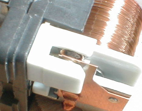 I sanded and cleaned the contacts (I'm from the days of points and condensers you know) then tested and reassembled. I now measure .1 ohms across the load terminals when closed. I do realize that the contacts are plated to resist corrosion and by sanding I removed what little plating might have been left. I expect the renewed life to be short. I'm going to replace the relay with a standard automotive 20A relay. Relay sizing is based PRIMARILY on the current capacity of the contact. Load voltage ratings are governed by the isolation of internal relay components. At stator voltages, this is a minor consideration. The stator is rated at 37 Amps (total from all three legs). I'm not sure what maximum current is present in one leg but a 20 Amp relay should be sufficient. I'll try one and check it regularly. It can't be worse than the HD one and I already know I can ride indefinitely with one stator leg disconnected as long as I don't use high beams. I've been doing so for thousands of miles. EDIT: I found a 40 Amp relay at Autozone for $6. I'll post if it dies an untimely death. (Message edited by pwillikers on January 22, 2012) | ||
Timebandit |
PW! Very interesting post! By any chance did you happen to test the impedance across the contacts before you filed them? I'm thinking that Z had to be really high. Your experience definitely supports the theory that I was discussing regarding relay failure modes. Superficially, the relay appeared to work when you listened for clunking, but the contacts were so badly damaged by the over-voltage over-current condition that the system wasn't working as intended. that's where the Impedance test for the contacts (or a voltage drop test) would be very useful. If your leg remained dead even with the contacts closed, then you had a 100% voltage drop. Wow. Regarding current ratings, I would look for a 25A or 30A relay if you can find one, or if you use a 20A relay, be sure to test and replace regularly. Bear in mind that that one stator leg controls TWO circuits, so there are times when that relay has to carry 2/3 of the system current. 38A * 2/3 = 25.3A. It's good to hear the confirmation that your low voltage at idle was caused by a relay problem. The good news is that the fix was cheap.  | ||
Samg |
Make sure the relay has a diode... Del city.com has relays with diodes | ||
Pwillikers |
Hey, this thing actually charges at idle now and I can use the high beams without draining the battery! I can't wait to try my electric vest. Woo hoo! Gemini, props to you for posting the harness upgrade logic documentation. It confirmed to me that mine was misbehaving. Facts are wonderful. TB, Thanks for keeping the quest to find a charging system fix alive and sensible. I edited the above post to answer your impedance question to keep all the info in one post. A couple points from your above post: "Bear in mind that that one stator leg controls TWO circuits," Agreed. "so there are times when that relay has to carry 2/3 of the system current. 38A * 2/3 = 25.3A." Really? Isn't the current evenly distributed across the three legs each carrying 1/3? | ||
Timebandit |
Yes, thanks to Gemini for posting the switching logic. that was a HUGE help to figuring this all out! Regarding PW's question, In a BALANCED 3-phase system, each leg conducts the same amount of current as the others, when averaged over time. What makes this confusing is that the amount of current flowing through any one wire changes instantaneously with phase angle. In our case, the relay takes a balanced 3-phase system and intentionally unbalances it. That makes things interesting. 3-phase setups aren't intuitive. The distribution of current in a 3-phase system depends upon phase angle for each of the two coils that are attached/conducting to the lead you're sampling, and the math gets complicated. Here is a link that covers the math: http://www.3phasepower.org/3phasepowercalculation.htm (Message edited by timebandit on January 23, 2012) | ||
Timebandit |
Make sure the relay has a diode... Del city.com has relays with diodes Or just modify your harness to add a diode across the right terminals to protect the ECM from back EMF. If you were to add a diode across the harness leads, then you would not have to shop for special relays. | ||
Dktechguy112 |
I want to order a new relay, is there a consensus on what relay should be used? | ||
Timebandit |
regarding the idea of buying a relay with a diode, since the ECM is already designed for relay control, I'd expect that it is already internally protected. at least that's what i'd have done if i were designing it. DK, i'd just go to my local auto parts store and see what they've got. | ||
Pwillikers |
From what source was it confirmed that the HD relay has a diode? (Message edited by pwillikers on January 22, 2012) | ||
Nightsky |
You want to choose a relay with contacts rated at least full stator current. Usually 2 stator legs out of 3 are passing full load current. Since relay contacts connect to a leg, they must also have full rating. Because only 2 stator legs are active at any time, average leg current is 2/3 of load. The shunt regulator ensures you draw max current. | ||
Timebandit |
i don't think it was ever confirmed that the HD relay has a Schottky diode. in fact, the TSB fails to show any diode in the schematic. the reason that the diode idea came up is because somebody (samg i think) brought up the idea that a suppression diode might be necessary to protect the ECM from flyback voltages. this is a valid concern. http://en.wikipedia.org/wiki/Flyback_diode i honestly think that HD should have/would have designed the ECM to have this sort of feature to protect the switching transistor in the ECM. but then I'd also expect that they'd place a properly sized cap across the contact side of the relay to prevent destruction by arcing. it doesn't look like they did that either. to determine whether or not a suppression diode is even necessary, all that you'd need to do is to scope the relay coils during switching and look for back EMF. | ||
Samg |
Time.. If you look at the diagram on the stock relay itself, it shows a diode. The diagram on the service bulletin does not show that diode.. | ||
Sparky |
I too was thinking of the old cars with points and condensor. The condensor (capacitor) helped to prevent excessive pitting of the points from switching the current on and off. Oh, but that was a DC application and we're dealing with an AC application here. But waddya think, if a cap was placed across the load terminals, might this idea work to prevent excessive pitting? | ||
Timebandit |
yes. that's why i said i was surprised that H-D didn't do it. evidently, they guy who designed the harness was either pinching pennies or he didn't understand why it needed to be done. | ||
Dannybuell |
What is the part # for the relay with the capacitor? | ||
Timebandit |
there is not part number. AFAIK you can't buy a relay with a suitable capacitor on it. the idea to put a cap there came from smart guys who understand theoretical benefits, but didn't crunch the numbers to determine practicability. I just crunched some numbers. the proper capacitor for this application, considering the voltage and current, would be HUGE. electrolytic only. short-lived in a high heat, high vibration environment. the capacitor would be big enough to be difficult to fit under the seat. it would cost more than the relay and it would introduce another point of failure that would be hard for the average user to recognize. it looks like simple preventive maintenance is still the best answer. you're expected to replace relays when they need to be replaced. that's the simplest and most cost-effective solution. the problem is that the relay is under the seat where people tend to forget about it. i'm still thinking that some sort of monitoring system (dashboard LED) would be helpful. overkill? maybe, but we all like status lights to tell us when there's a problem. (Message edited by timebandit on January 24, 2012) | ||
Dktechguy112 |
"Looking at the DC output on the instrument cluster really won't help you recognize a problem until it's too late. You'll only see low voltages on the instrument cluster after things have been going bad for a long time. " I have a brand new stator on the bike with less then 400 miles on it, that shows an idle voltage of 12.1-12.3, how can it be to the point of failure? I should also note that the battery and voltage regulator were replaced with the stator. | ||
Dktechguy112 |
Looking at the parts manual, I see two p/n for relays: 31522-00C MICRO RELAY, SPDT, W/DIODE Y0175.1AM RELAY, TYCO MINI ISO Only 31522-00C mentions the diode, is that the relay p/n for the charging harness? |