| Author | Message | ||
Blaylock1988 |
I posted this over on BuellXB but wanted to post it here too.
Right now I am looking at skipping LabVIEW and possibly just doing all of the programming on the Ardiuno (I will have to teach myself C+ which I have been interesting in learning anyways) (Message edited by Blaylock1988 on February 16, 2012) | ||
Reepicheep |
I think the ECM is actually a PIC. I forget where I saw a hint of that, but it stuck in my mind. If you want to use a PIC instead of an Audrino (both good, the PIC is cheaper if you want to make a bunch of them) I can help you out with programmers, schematics, and source code. I hope its C, and not C++. C++ would be overkill for an embedded system. | ||
Blaylock1988 |
I spoke with another guy and he said it was CAN protocol. Wikipedia says that the Arduino comes with a C/C++ library called "wiring" and that programs are written in C/C++. I guess that means either of the two languages are used? I don't know anything about PICs though. I am only planning on making one for the project, and giving the code to people who want to do it. | ||
Msamuels0 |
You don't need CAN... The diagnostic connector has a nice, simple TTL-level UART right on it. (The 4 pins are power, gnd, TX, and RX). I can't remember the baud rate off the top of my head, though. You basically send a command that replies with a 100-something byte response which pretty much dumps all the data in that one message, so you just parse out what you need. I've made a PIC-based dash "accessory", (PIC24FJ256GB010, made PCB's, rapid-prototyped enclosures, did firmware, etc) which is basically a 4.3" touchscreen, where I have selectable customizable gauges to show whatever parameter I want to pull up. Works awesome on my XB9SX. (I'm an EE by profession). Take a look at the ECMSpy stuff... they have pretty much all the info you'd need called out for the protocol, should be easy enough to implement in any micro. | ||
Blaylock1988 |
MSamuels0, do you have any pictures or videos of your dash accessory? I would love to see how it works! I ordered an Arduino and I am going to run through tutorials and learn the programming (I pick stuff up pretty quick and it will be the 4th programming language I have taught myself) The thing I know will be the hardest for me is figuring out how to get the data from the ECM into the Arduino so I can do what I want with it. I know the Arduino has TX and RX connectors on it and I am hoping I can connect to the ECM by adapting the ECMSpy cable, but I only remember that cable having 3 connectors, not 4 like you mentioned. I am an ME so I don't have any experience with micro-controllers, but this is a good learning experience for me and I look forward to it. I really appreciate any help that anyone can offer. | ||
Msamuels0 |
Don't have it "installed" at the moment, so just popped off the seat and plugged it in right at the diagnostic connector, still running some of my development/testing firmware. Sorry, couldn't really get a decent video of it actually operating, but it really does work! Couple of jumper wires on my board, because I made a few mistakes on the first layout. Most of the electronics are just to drive the display. Also added in a microSD card for any kind of datalogging, and USB connectivity to upload/configure/whatever. The empty footprint is for a bluetooth module I've used on other projects, just hadn't populated it on this board yet. As far as the 3 wires vs. 4 wires on the diagnostic cable, the pre-made cables that you can buy generally don't have the +12V on them (they're USB-powered), just TX, RX, and ground, which is all you need to do the UART communcations. 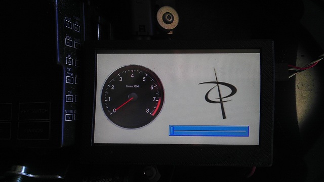 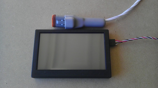 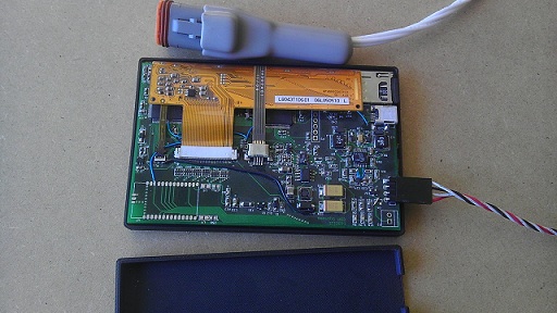  | ||
Blaylock1988 |
Wow that is awesome! I wish I knew enough to do stuff like that. So I could connect that 4th pin with a voltage regulator and power the Arduino/screen with it. I ordered an Arduino and a small character LCD so I can practice and learn the language until I learn how to retrieve data from the ECM. | ||
Msamuels0 |
That's exactly what I did... I used the +12V provided on the diagnostic connector, to go to a voltage regulator on my board to provide the voltage rails I needed. I've never played around with the Arduino (but have used Atmel micros before), so I might not be able to answer Arduino-specific questions, but if you have any questions about the serial stream, I could probably help with that. Good luck! | ||
Reepicheep |
Very cool stuff Mark, thanks for sharing that. | ||
Djohnk |
That would be cool to have virtual gauges like that ... You could monitor whatever your heart desired, like engine temp etc. Was thinking of hooking up a tablet PC via a blue tooth module (Windows 8 Tablets are coming out this year -- they might run ECMspy and Megalogtuner), or doing something like you are doing Msamuels0. One thing I wonder about is the visibility of those LCD screens in full sunlight. I suspect they don't work well. I have been outside with my laptop resetting the TPS, and couldn't see the screen very well due to the intense sunlight. | ||
Msamuels0 |
Sunlight readability was definitely a concern... I don't think I've ever used my ipad or touchpad outdoors, but they'd probably wash out quite a bit. The display I decided to use is a touchscreen version of the same display that was in the sony PSP, which looked decent in the sunlight. I'd love for some OLEDs to be made available in mass quantities of that size... would totally be worth redesigning for the new display, because it would look AMAZING, sunlight or no. | ||
Blaylock1988 |
Ok, so I got my Arduino and started learning C/C++ and it is very similar to other languages I have used before. I am reading on ECMSpy's website on how to communicate with the ECM. It says: A communication channel to the ECM is established by setting up a serial link using these settings: 9600 bits per second (I know this is the baud rate) 8 databits 1 stopbit no parity no flow control TTL voltage levels (logical 0 <0.8> 2.0 volts). Voltage must not exceed 5.0 volts! It looks like I don't need to read from the EEPROM, I need to read the Runtime information from the DDFI-2. So if I wanted to read something like engine RPM which is offset 11, would I write to the TX pin: Byte # Meaning Values (typical) Remarks 1 SOH 0x01 Start of Header 2 Emittend 0x00 From PC 3 Recipient 0x42 To ECM 4 Data Size 0x05 5 Bytes 5 EOH 0xFF End of Header 6 SOT 0x02 Start of Text 7 Data 1 0x52 = Get 0x57 = Set Command 8 Data 2 0x00 Page Offset 9 Data 3 0x01 Page No. 10 Data 4 0x01 Number of Bytes 11 Data 5 (EOT) 0x03 End of Text 12 Checksum 0xEB XORed Checksum where the offset is 0x11? Also, this is all in Hexidecimal, how would this be typed into C so it can be transmitted as Hex? | ||
Starwolve |
Has anyone taken a look at the Raspberry Pi? (http://www.raspberrypi.org/) It looks like this small platform might be ideal for simple projects where space is at a premium. I'm thinking about getting one (once they're available again - it seems like the websites for ordering crashed when they were opened) and seeing what I can do with it to make a small onboard computer for my XB. | ||
Reepicheep |
// Define a variable that will store one byte unsigned char foo; // set that variable to hex 11 foo = 0x11; | ||
Reepicheep |
The C Compiler recognizes the 0x start to the constant, and interprets the string as base 16. You can also do it in binary (0b00010001) or in octal (021). There are always 8 bits (1 or 0) in a byte. The "unsigned" directive says you want your byte (called a char in C) to represent a number between 0 and 256. A signed character gives up one of your bits to indicate positive or negative, so a signed char can go from -127 to +128 (I'd have to look it up to be sure). You also have to worry about a byte "rolling over". 0xFF (255) plus 0x01 (1) is not 256... its 0. So you have to be careful adding or subtracting. | ||
Blaylock1988 |
That Raspberry Pi looks pretty neat. I found that I actually type in each part of the serial as 0x11. I have seen that word "foo" before but I don't know what it means. I think the code I will have to send will look something like this: mySerial.print(0x01, 0x00, 0x42, 0x02, 0xFF, 0x02, 0x52, 0x00, 0x01, 0x11, 0xEB, HEX); and I should expect a response back from the ECM that looks similar. | ||
Msamuels0 |
The serial string that you've got formatted there, is formatted to read the EEPROM, not the real-time data. If you send out the following string: {0x01, 0x00, 0x42, 0x02, 0xFF, 0x02, 0x43, 0x03, 0xFD} (I'll leave that to you to decode... hint, look at the very bottom table on http://www.ecmspy.com/eeprom_info.shtml) That will reply with a 100+ byte stream of all the runtime data, byte #11 of which, is what you'd want to look for and save off. Edit: actually, if you want RPM, that would be two bytes, made up of the bytes at positions #11 and #12 (16-bit value) -Mark (Message edited by msamuels0 on March 01, 2012) | ||
Blaylock1988 |
Ok, thanks. So the real-time data is on the virtual page? That makes it easy since I don't really need anything from the EEPROM (unless I decide to tune it via Arduino later on) so I wont need to worry about trying to figure out which page the info I need is on. I do remember RPM saying it is a two byte data. I have my LCD working with the Arduino so when I get home I will try read the data and get it to display on the LCD. Edit: I just realized that you meant that when I request run-time data, it will send out ALL run-time data at once, and I pick and choose the offsets that I want. That actually makes things much easier since I don't have to send out mass amounts of request codes. Edit:Edit: Which model Buells have a DDFI-III ECM? (Message edited by Blaylock1988 on March 01, 2012) (Message edited by Blaylock1988 on March 01, 2012) | ||
Msamuels0 |
Yep, sending that one command gives you a dump of everything at once. Not sure which models have which ECM, but you can always check the length byte of the received response, and use that to differentiate, since the ECM's provide different amounts of parameters between them. -Mark (Message edited by msamuels0 on March 01, 2012) | ||
Blaylock1988 |
So when I get the bytes I need, how do I convert from Hex to base 10 numbers in C/C++? Edit: I just noticed on the ECMSpy site it says only 2008 and newer use DDFI-3. This is unfortunate because the DDFI-2 ECM doesnt have intake manifold pressure. This means I may need to install a barometric sensor, and I really don't want to do anything intrusive with my engine. (Message edited by Blaylock1988 on March 01, 2012) | ||
Msamuels0 |
I'm assuming that the Arduino C libraries probably have "printf" support, which you can use to generate a string of the decimal representation, that you can then send to your LCD. If so, that's probably the easiest way. -Mark | ||
Blaylock1988 |
You are right, I can do lcd.print(data, BASE) Which will be enough to verify that I am receiving the correct information, however, I need to perform very large calculations to the numbers I get from the ECM. Simply displaying them isn't enough for the purposes of the project. | ||
Msamuels0 |
All of your calculations can (and most likely would) be done in hex anyway. You really don't need to convert to decimal until something is ready to be displayed, and be human-readable. | ||
Blaylock1988 |
After I send the request code, and the ECM sends back the steam of data, how do I pick and choose the 11th and 12th byte, then combine them to display in C? | ||
Reepicheep |
Allocate a big array of unsigned characters for it, and just use an array index. // allocate 512 bytes unsigned char foo[512]; // copy from source into it (you will use something else, but this gives you the idea) memcpy(foo, source, 512); // Access the 11th byte (indexes from 0, not 1, so subtract 1 from the offset you want) printf("Byte 11 is %x\n", foo[10]); | ||
Blaylock1988 |
SUCCESS! I got the Arduino to send the request series data, and read and displayed the data that came back on my LCD. I can see the first 16 characters (in Hex) and can see the exact characters for the header and a few more for the run-time data. Now to separate the data. I am very new to C/C++ so the stuff that Reepicheep said looks very foreign to me. Also, the offset list is already sorted from 0 to 106. Here is the code I have so far: http://arduinobuell.blogspot.com/p/code.html | ||
Blaylock1988 |
Im having some trouble with the data from the ECM. I am able to pick and choose the data, but I am getting a 10 byte response telling me an error.  This is the Hex code I get from the ECM: 1 //start of header 42 //to PC 0 //from ECM 3 //size of data FF //end of header 2 //start of text 15 //ERROR (because it isn't 06 which would mean success) 41 //the rest of the error? 3 //end of text EB //checksum so my error code is 1541 in hex Help? (Message edited by Blaylock1988 on March 04, 2012) | ||
Msamuels0 |
Your command has the wrong checksum... The string I quoted above has the correct checksum (0xFD) for this message. The string you're sending has 0x43 as the command to get runtime data, but the checksum that you're sending (0xE8) is what the checksum would be if the command was 0x56. Try the string I suggested, and see what you get. -Mark | ||
Blaylock1988 |
Ohhhhhhhh. The EcmSpy site doesnt say to use the alternative checksum. Dang, well I'm glad its an easy fix. I am going to Myrtle Beach this week for Spring Break so I will have to test it out next Saturday when I get back. Also, no internet in the house we are staying at. | ||
Msamuels0 |
A checksum, by definition, is going to change if any of the data in the message changes... That table on the ECMSpy website states that the checksum is an XOR of all the preceding data, but doesn't state that it only includes everything after the first byte (0x01). So, to verify the checksum the following message from the ECMSpy table: 0x01 0x00 0x42 0x02 0xFF 0x02 0x56 0x03 Take what's after the 0x01, leaving: 0x00 0x42 0x02 0xFF 0x02 0x56 0x03 If we do the XOR operation on the first two bytes, then keep XORing the result with the next byte: 1. 0x00 ^ 0x42 = 0x42 2. 0x42 ^ 0x02 = 0x40 3. 0x40 ^ 0xFF = 0xBF 4. 0xBF ^ 0x02 = 0xBD 5. 0xBD ^ 0x56 = 0xEB 6. 0xEB ^ 0x03 = 0xE8 So, 0xE8 is the correct checksum for that specific message. To calculate the checksum for the message which requests runtime data: 0x01 0x00 0x42 0x02 0xFF 0x02 0x43 0x03 Drop the first byte, leaving: 0x00 0x42 0x02 0xFF 0x02 0x43 0x03 Do the byte-by-byte XORing: 1. 0x00 ^ 0x42 = 0x42 2. 0x42 ^ 0x02 = 0x40 3. 0x40 ^ 0xFF = 0xBF 4. 0xBF ^ 0x02 = 0xBD 5. 0xBD ^ 0x43 = 0xFE 6. 0xFE ^ 0x03 = 0xFD So, the checksum for this specific message is 0xFD. The point of a checksum is to verify the integrity of the previously received data, so once the ECM receives the complete message, it calculates the checksum byte-by-byte, and if it doesn't match the checksum that was appended to the end of the data, rejects the whole thing as bad/corrupt, and apparently sends an error response. Hope that helps explain it. -Mark |