| Author | Message | ||
José_Quiñones |
Here are some of the pictures and descriptions of the patents that HD obtained during the development of this bike, which never went to production. If you want to see what the bike looked like, buy the August 2002 issue of American Rider | ||
José_Quiñones |
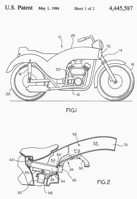 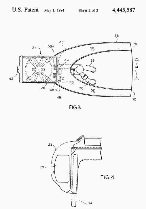 United States Patent 4,445,587 Hillman May 1, 1984 -------------------------------------------------------------------------------- Motorcycle cooling system Abstract A cooling system for the internal combustion engine of a motorcycle includes a radiator and means defining air passages each having a forwardly facing inlet opening disposed respectively on the opposite sides of the motorcycle's front fork. Each air passage extends rearwardly from the inlet opening to an outlet which opens into a plenum chamber disposed adjacent the radiator. The cross-sectional area of each passage increases gradually between its inlet and outlet ends. An exhaust duct is connected to the plenum chamber and the radiator is disposed between the plenum chamber and the exhaust duct. -------------------------------------------------------------------------------- Inventors: Hillman; Michael J. (Fox Point, WI) Assignee: Harley-Davidson Motor Co., Inc. (Milwaukee, WI) Appl. No.: 331132 Filed: December 16, 1981 Current U.S. Class: 180/229; 123/41.01; 123/41.48; 165/44; 165/51 Intern'l Class: B62D 061/02; B60K 011/04 Field of Search: 165/122,51 180/219,225 123/41.48,41.33 -------------------------------------------------------------------------------- References Cited [Referenced By] -------------------------------------------------------------------------------- U.S. Patent Documents 4019595 Apr., 1977 Imai et al. 180/229. 4354570 Oct., 1982 Tanaka 180/219. 4396086 Aug., 1983 Hattori 180/229. Foreign Patent Documents 1192537 May., 1964 DE 165/51. Primary Examiner: Cline; William R. Assistant Examiner: Streule; T. W. Attorney, Agent or Firm: Wiviott; Fred -------------------------------------------------------------------------------- Claims -------------------------------------------------------------------------------- I claim: 1. A motorcycle including front and rear forks for mounting front and rear wheels respectively, a frame interconnecting said forks, a liquid cooled internal combustion engine and a radiator for said engine supporting on said frame and between said forks, the improvement comprising an air transport system for said radiator including: means defining first and second air passages each having a forwardly facing inlet opening disposed respectively on the opposite sides of said front fork, each air passage means extending rearwardly from its inlet, means defining a plenum chamber disposed adjacent said radiator, said air passages having an outlet opening into said plenum chamber, the cross sectional area of each passage increasing gradually between its inlet and outlet ends, an exhaust duct connected to said plenum chamber, said radiator being disposed between said plenum chamber and said exhaust duct and creating a substantial resistance to air flow therebetween. 2. Cooling system set forth in claim 1 wherein each of said air passages curves inwardy and downwardly as it progresses from said inlet openings to said plenum chamber. 3. The motorcycle set forth in claim 2 wherein the cross sectional area of said radiator facing said plenum chamber is about four times the combined areas of said inlets. 4. The cooling system set forth in claims 1, 2 or 3 wherein said exhaust duct extends downwardly, said radiator being oriented in a slight inclined angle from front to rear and being disposed between said plenum chamber and said exhaust duct. 5. The cooling system set forth in claim 4 wherein said air passages each have a first portion adjacent its inlet end and a second portion adjacent its outlet end; the rate of increase in a cross sectional area per incremental length of said air passages is substantially greater in the second portion than in the first portion. 6. The cooling system set forth in claim 5 wherein each of said inlets is generally rectangular and has a height of about twice its width. 7. The cooling system set forth in claim 6 wherein said radiator includes a plurality of heat exchange tubes disposed in general parallelism and a header disposed at each of the opposite ends of said tubes, a divider in the first header dividing the same into first and second chambers, a cooling water inlet pipe connected to one of said chambers and a water outlet pipe connected to the other chamber, said pipes extending forwardly of said radiator and being connected to said engine. 8. A cooling system for a liquid cooled motorcycle engine including a radiator for dissipating heat from the engine cooling liquid, first and second conduit means each defining air passages and having an inlet opening spaced one from the other and from said radiator, means defining a plenum chamber disposed adjacent said radiator, said conduit means each extending from its inlet opening to said plenum chamber and having an outlet opening into said plenum chamber, the cross sectional area of each passage increasing gradually between its inlet and outlet ends, an exhaust duct connected to said plenum chamber and extending downwardly therefrom, said radiator being disposed between said plenum chamber and said exhaust duct and creating a substantial resistance to air flow therebetween. 9. The cooling system set forth in claim 8 wherein said radiator is inclined upwardly at a slight angle relative to the plenum chamber, and means sealing the periphery of said radiator relative to said plenum chamber and exhaust duct. 10. The cooling system set forth in claim 9 wherein the area of said radiator facing said plenum chamber is about four times the combined areas of said inlet openings. 11. The cooling system set forth in claims 8, 9 or 10 wherein the pressure drop across said radiator is about 25-80%. 12. The cooling system set forth in claim 11 and including a fan disposed in said exhaust duct and adjacent said radiator. 13. The cooling system set forth in claims 8, 9 or 10 wherein the pressure drop across said radiator is about 50%. -------------------------------------------------------------------------------- Description -------------------------------------------------------------------------------- BACKGROUND OF THE INVENTION This invention relates to motorcyles and more particularly to a motorcyle cooling system. In the prior art, motorcycle engines have been both air and water cooled. When water cooling is employed, sufficient ambient air must be passed through the radiator to satisfy the cooling requirements of the engine. This has created design problems in that the bow wave created by the front portions of the motorcyle such as the fork, the fairing, the fender, and the headlight, tend to divert the air stream outwardly of the radiator, particularly when the same is mounted forwardly of the engine. As a result, radiators mounted in this manner tended to be relatively inefficient requiring a comparatively larger physical size. SUMMARY OF THE INVENTION The primary object of the invention is to provide a cooling system for motorcycle engines. A further object of the invention is to provide a cooling system for liquid cooled internal combustion motorcycle engines which delivers sufficient air to the radiator to satisfy engine cooling requirements. Another object of the invention is to provide an air collection system for motorcycle internal combustion engine cooling systems which does not detract from the aesthetic appearance of the vehicle. A still further object of the invention is to provide a cooling system for a liquid cooled motorcycle engine wherein heated air does not pass over the operator or a passenger. Yet another object of the invention is to provide a cooling system for a liquid cooled motorcycle engine wherein improved radiator efficiency is achieved. These and other objects and advantages of the present invention will become more apparent from the detailed description thereof taken with the accompanying drawings. In general terms, the invention comprises a motorcyle including front and rear forks for mounting front and rear wheels, respectively, a frame interconnecting said forks, a liquid cooled internal combustion engine and a radiator for said engine supported on said frame and between said forks. The improvement comprises an air transport system for said radiator which includes means defining first and second air passages, each having an inlet disposed respectively on the opposite side of the forks. Each air passage extends rearwardly from its inlet and has an outlet opening into a plenum chamber disposed adjacent the radiator with the cross sectional area of each air passage increasing gradually from its inlet to its outlet ends. An exhaust duct is connected to the plenum chamber with the radiator disposed between the plenum and the exhaust duct. BRIEF DESCRIPTION OF THE DRAWINGS FIG. 1 is a side elevational view of a motorcycle incorporating the invention; FIG. 2 is a side view, with parts broken away, of the cooling system according to the invention; FIG. 3 is a plan view, with parts broken away of the cooling system shown in FIG. 2; and FIG. 4 is a front view of one portion of the cooling system shown in FIGS. 2 and 3. DESCRIPTION OF THE PREFERRED EMBODIMENT FIG. 1 shows a motorcycle 10 which incorporates the cooling system in accordance with the preferred embodiment of the invention and includes a frame 12 having a front fork 14 and a rear fork 16 to which front and rear wheels 18 and 20 are respectively mounted in a conventional manner. A watercooled, internal combustion engine 22 is mounted on frame 12 and is coupled to rear wheel 20 in a manner well known in the art to provide motive power for the motorcyle 10. A body 24 is mounted on the frame 12 above the engine 22 and encloses a gas tank and an air cleaner (not shown) in addition to the cooling system in accordance with the preferred embodiment of the invention. As seen more particularly in FIGS. 2 and 3, the cooling system 24 for the engine 22 includes a radiator 26, engine coolant outlet and return pipes 28 and 30 for coupling the radiator 26 to the engine 22 and an air flow system 32 for delivering ambient air to the radiator 26 for the exchange of heat with the engine cooling fluid therein. The radiator 26 is generally rectangular in plan view and includes a plurality of finned tubes 38A and 38B extending between headers 40 and 42. The engine coolant outlet and return pipes 28 and 30 are connected to the header 40 on the opposite sides of a partition 44 which divides header 40 into an inlet chamber 46 which communicates with tubes 38A and a return chamber 48 which communicates with tubes 38B. As a result, engine coolant flows from the engine 22 through pipe 28 into chamber 46 for passage through tubes 38A to header 42, and then back through tubes 38B to chamber 48 for return flow to engine 22. It can be seen that by coupling the engine outlet and return pipes 28 and 30 to the side the radiator 26 nearest engine 22, these connections can be maintained without interference with the air flow in system 32. The air flow system 32 is disposed within the body 23 and includes a pair of air passages 50 and 52 which are formed of sheet metal and extend from the front of the body 23 rearwardly where they merge into a plenum chamber 54. The radiator 26 lies below the plenum chamber 54 and is inclined from front to rear at a slight vertical angle. An exhaust duct 60 which is also formed of sheet metal communicates with the opposite side of the radiator 26 and extends generally downwardly therefrom. Those portions of the plenum 54 and the duct 60 adjacent the radiator 26 are configured similarly to the generally rectangular upper and lower margins thereof and are sealed thereto by seals 62 and 64 so as to form a continuous passage intersected by the radiator 26. A fan 66 is disposed within exhaust duct 60 adjacent the radiator 26 and is driven by a motor 68 to assist in the cooling air flow. The downwardly oriented exhaust duct 60 insures that heated air from radiator 26 will not flow over the operator or a passenger. The passages 50 and 52 are identically formed with one being the mirror image of the other and both curve rearwardly and downwardly in the side view shown in FIG. 2 and rearwardly and inwardly in plan view as shown in FIG. 3. At the front of each duct 50 and 52 is an inlet opening 70 disposed outwardly of the front fork 14. The inlet openings 70 are preferably generally rectangular as shown in FIG. 4 with a height to width ratio of about 2 to 1 which is similar to at least the initial portions of passages 50 and 52. From the inlet opening 60 there is a gradual increase in the height and width of each duct 50 and 52 until their merger at plenum 54. This gradual increase in cross sectional area of air passages 50 and 52 is such that the combined areas of the inlet openings 70 are at about one-fourth of the cross-sectional area of the radiator 26. It can also be seen that the rate of increase in area is greater in those portions of the passages 50 and 52 which are adjacent their outlet ends. The inlet openings are also positioned such that they are outside the bow wave formed in the air stream by the front fork 14. Additionally, the radiator 26 is chosen so as to have a substantial air flow resistance whereby back pressure in the air passages 50 and 52 minimizes turbulence therein. In practice, it has been found that the pressure drop should be about 25-80% and preferably about 50%. The air flow system 32 improves radiator efficiency thus permitting a smaller radiator to be employed than is the case with motorcycles having a radiator mounted forward of the engine. While only a single embodiment of the invention has been illustrated and described, it is not intended to be limited thereby but only by the scope of the appended claims. | ||
José_Quiñones |
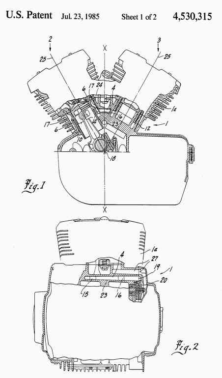 United States Patent 4,530,315 Mezger July 23, 1985 -------------------------------------------------------------------------------- Cylinder block Abstract A one-piece cylinder block for a water-cooled internal combustion engine with two rows of cylinders in a V-arrangement has a longitudinal duct for supplying cooling water. The block is preferably made by a diecasting process. The longitudinal duct is connected to the coolant spaces of the cylinders which are located between a cylinder sleeve and an outer jacket surrounding the latter. The longitudinal duct is disposed between the rows of cylinders in the cylinder block and at least one opening is provided in the region of the coolant spaces for each cylinder. These openings are cast in the casing walls of the cylinder block. Since they are disposed directly adjacent the longitudinal duct, they extend essentially radially to the cylinders. -------------------------------------------------------------------------------- Inventors: Mezger; Hans (Freiberg, DE) Assignee: Harley-Davidson Motor Co., Inc. (Milwaukee, WI) Appl. No.: 630704 Filed: July 13, 1984 Foreign Application Priority Data -------------------------------------------------------------------------------- Jul 21, 1983[DE] 3326317 Current U.S. Class: 123/41.74; 123/41.79 Intern'l Class: F01P 003/02 Field of Search: 123/41.72,41.74,41.79,41.83,41.02 -------------------------------------------------------------------------------- References Cited [Referenced By] -------------------------------------------------------------------------------- U.S. Patent Documents 2654355 Oct., 1953 Scheiterlein 123/41. 4082068 Apr., 1978 Hale 123/41. Foreign Patent Documents 648930 Jul., 1937 DE2. J 8282 Jan., 1956 DE. 2015546 Nov., 1970 DE 123/41. 2553291 Apr., 1979 DE. 58-51244 Mar., 1983 JP 123/41. Other References "M.G.O. Quick-Running Engines", Diesel Railway Traction, Apr., 1961, pp. 135-137. Primary Examiner: Cuchlinski, Jr.; William A. -------------------------------------------------------------------------------- Claims -------------------------------------------------------------------------------- I claim: 1. A one-piece die cast cylinder block for a water-cooled internal combustion engine having a crankshaft and which includes two rows of cylinders in a V arrangement, said block including a longitudinal duct for supplying the cooling water for said engine, said duct being connected to the coolant spaces of the cylinders which are located between a cylinder sleeve and an outer jacket part surrounding said sleeve, said longitudinal duct being disposed between the rows of cylinders of the cylinder block in the region of the coolant spaces for each cylinder, openings cast in a casing wall of said cylinder block, said openings being disposed directly adjacent the longitudinal duct and extending essentially radially to the cylinder, said longitudinal duct being disposed in a vertical longitudinal center plane of said cylinder block, said plane extending through the crankshaft axis of said engine, said longitudinal duct being trapezoidal in cross-section, the longer side of the trapezium being directed upwardly and the lateral faces of said trapezium of said duct extending approximately parallel to the axis of a corresponding cylinder, said longitudinal duct extending approximately as far as the rear cylinders of said engine of each row and wherein a cooling water pump is connected to the outer aperture of said duct. 2. A one-piece die cast cylinder block for a water-cooled internal combustion engine having a crankshaft and which includes two rows of cylinders in a V arrangement, said block including a longitudinal duct for supplying the cooling water for said engine, said duct being connected to the coolant spaces of the cylinders which are located between a cylinder sleeve and an outer jacket part surrounding said sleeve, said longitudinal duct being disposed between the rows of cylinders of the cylinder block in the region of the coolant spaces for each cylinder, openings cast in a casing wall of said cylinder block, said openings being disposed directly adjacent the longitudinal duct and extending essentially radially to the cylinder, said coolant space of each cylinder being annular in shape and extending as far as a transverse center plane of the cylinder, in which plane said openings of said longitudinal duct open into the respective coolant spaces, said openings being rectangular in the area where they are coupled to the coolant spaces, a casing wall enclosing the cylinders in a circular manner and in each case including a second duct with a U-shaped cross-section which opens into said openings and which extends in an upward direction parallel to the axis of the cylinder and which is open towards said coolant spaces. 3. The invention set forth in claim 2 wherein the inner faces of said openings extend in the base of said second duct in one plane with the inner lateral face of said longitudinal duct, in such a way that in the overlap region of the longitudinal duct, the second duct openings are formed. -------------------------------------------------------------------------------- Description -------------------------------------------------------------------------------- BACKGROUND OF THE INVENTION 1. Field of the Invention The present invention relates generally to the art of cylinder blocks for internal combustion engines, and more particularly, to the cooling of such engines. 2. Description of the Prior Art In a known cylinder head (German patent specification No. 29 04 167), produced by the diecasting process, the cooling water ducts are formed by integrally cast pipes. The pipes are connected to one another and extend transversely over the entire cylinder block towards the cooling spaces. The pipes typically have a relatively great length. In the regions in which they are in contact with the cooling spaces in the cylinder block, passage openings are provided. Such a construction of the cooling water ducts is advantageous because the ducts have a defined cross-section. However, such an arrangement of pipes in a cylinder block is very hard to produce in a diecasting process. Moreover, the coolant is supplied to the cooling spaces of the cylinders transversely over the cylinder block. Because of the flow path, the flowing cooling medium may already be heated before it reaches the space adjacent the cylinders. In other known constructions, in which integrally cast pipes are not used in the cylinder block or head, ducts with outer apertures result from the casting technique. These must be closed by means of additional stoppers, covers or the like. OBJECTS AND SUMMARY OF THE INVENTION It is a primary object of the present invention to provide a cylinder block water cooling system which provides selective cooling of the regions of the cylinders which are subjected to high heat stress. Another object of the present invention is to provide an arrangement of cooling water ducts in a cylinder head or block which can be easily produced using permanent cores in a high pressure casting process. A further object of the present invention is to provide a cylinder block which requires no substantial finishing after production in a casting process. How these and further objects of the invention are accomplished will be described in the following specification, taken in conjunction with the drawings. Generally, however, they are accomplished by a cylinder block design which has defined cross-section cooling water ducts and no pipes. Openings to the coolant spaces of the cylinders are provided to a longitudinal duct, the openings being produced during the casting process. This is accomplished by shaping the casing wall adjacent the longitudinal duct so that a shaped portion thereof projects into the longitudinal duct and causes a penetration in this region during casting. The longitudinal duct is arranged between the rows of cylinders to shorten the path to the coolant spaces, resulting in water of equal quantity and temperature being provided to each cylinder. As a result of the efficient cooling of the cylinders, engine efficiency is increased, emission problems are reduced and fuel consumption is decreased. The longitudinal duct has a single outer aperture which is connected to the cooling water pump, which in turn is connected to the water reservoir by a supply line. This duct connection of the pump to the aperture further insures that the cooling fluid is supplied directly to the longitudinal duct and into the coolant spaces. By using this type of construction, closures such as covers, stoppers or the like, as used in the prior art, are not required. Re-usable cores may be employed in the diecasting process and finishing work is not necessary. The ducts and openings are precisely produced. The openings are produced by means of the adjoining cores in the opening region. In the preferred embodiment the longitudinal duct is trapezoidal in cross-section, with its lateral walls extending parallel to the cylinders. Also the casing wall includes a U-shaped duct in the region of the openings so as to provide an approximately rectangular opening to maximize flow for the cooling medium. DESCRIPTION OF THE DRAWINGS FIG. 1 is a cross-section through an internal combustion engine showing a longitudinal duct and a plurality of coolant spaces; FIG. 2 is a longitudinal section through the internal combustion engine shown in FIG. 1; FIG. 3 is a diagrammatic horizontal section of the longitudinal duct of the cylinder block shown in FIG. 1, showing the openings into the coolant spaces of the cylinders; FIG. 4 is a horizontal section through a U-shaped duct in an inner casing wall of the coolant space of the internal combustion engine; and FIG. 5 is an enlarged diagrammatic representation of the trapezoidal longitudinal duct shown in the previous FIGURES. DESCRIPTION OF THE PREFERRED EMBODIMENT A one-part cylinder block 1 for a water-cooled internal combustion engine has two rows of cylinders 2 and 3 which are disposed in a V-shape. Between these two rows of cylinders 2 and 3, there is provided a longitudinal duct 4 which has openings 13, 14, 15, 16 to the individual coolant space 5, 6, 7 and 8 of the individual cylinders 9, 10, 11 and 12. The coolant spaces 5-8 extend in an annular manner around the cylinders 9 to 12 and are defined outwardly by a wall 17 of the casing wall of the cylinder block 1. The longitudinal duct 4 is preferably disposed in a vertical longitudinal center plane (X--X) extending through the crankshaft axis 18. It extends in the longitudinal direction approximately as far as the two rear cylinders 9 and 11 and is closed at this point. At the end of duct 4 opposite this closure, an outer aperture 19 is provided which is connected to a cooling water pump 20. Pump 20 is connected to a cooling water inlet 21. The longitudial duct 4 is preferably trapezoidal in cross-section with the longer side of the trapezium being directed towards the cylinder head 1a. Openings 13 to 16 are provided in its lateral walls 21 and 22 at a distance behind one another corresponding to the spacing between the cylinders. The openings extend directly from the longitudinal duct 4 in a transverse manner and open into the corresponding coolant spaces 5, 6, 7 and 8, to provide a short path during which the coolant is exposed to heat. Each coolant space 5 to 8 is provided in the vicinity of its respective openings 13 to 16 with a duct 24 having a U-shaped cross-section. Duct 24 extends in an upward direction (FIG. 4). The inner face 26 of duct 24 extends parallel to the cylinder axis 25 and to the lateral wall face 21 or 22 of the longitudinal duct 4. This duct 24 is shaped and positioned with respect to the longitudinal duct such that during casting, the openings 13 to 16 are produced by the cores in their overlap region. These openings are approximately rectangular and have an opening face inclined towards the course of the inner face 26. The openings 13 to 16 are located in such a way, with respect to the coolant spaces 5 to 8, that they open at the base 23. Thus the lower, shorter face of the trapezoidal longitudinal duct 4 extends approximately in one plane with the face of the base 23 of the U-shaped duct 24. Because of the arrangement of the longitudinal duct 4, extending in a horizontal plane, and of the coolant spaces 5 to 8, and because the U-shaped ducts extend in a plane inclined to the vertical, simple production is possible. The cores may be readily removed from the ducts because they are unobstructed. The cooling medium is fed from the radiator (not shown) by way of the line 27 of the cooling water pump 20 and is then conveyed into the longitudinal duct 4. From the duct, it is fed through the openings 13, 14, 15 and 16 directly to the respective coolant spaces 5, 6, 7 and 8 without being diverted. After flowing around the cylinders, the cooling medium is returned. The arrows shown in FIG. 3 indicate essentially the flow path. | ||
Spiderman |
We'll call it the B-Rod  | ||
Lake_Bueller |
Interesting to say the least. However, the radiator looks to be under the seat. Holy HOT Ass Batman  | ||
José_Quiñones |
It has a fan (26) that ducts the hot air away from the rider to the ground. | ||
Raymaines |
I just finnished that artical and it was pretty interesting. Funny how fate works. Like the man said "We're certainly not unhappy in the way our fortunes have gone. But still, you have to wonder what if...... | ||
Blacksix |
Would someone please scan that damn article and post it with pictures if possible? I can't find the magazine anywhere. Guess they short shipped or they are all sold out. lol | ||
José_Quiñones |
Here's the cover to wet your appetite...  | ||
Blacksix |
Alright....dammit.... I've searched all over town. All three big book stores. Can't find it and I want to see this bike! Help! | ||
Mikej |
Blacksix, Sometimes the little handi-marts and grocery stores carry the magazines that the Barnes&Nobles and BordersBooks don't carry. Don't know what you have around Tyler TX, but someone has to have it. Or, contact the magazine directly and ask if they'll send you a complementary copy of that issue, or if they know where their distrubutors distribute to locally to you. | ||
Davegess |
I'd post it except mine disapeared at work and th eidtor Buzz Buzzelli is a buddy of mine and the mag does really need the sales so that he can stay employed and not move back here to Milwaukee to bother me  | ||
Jima4media |
I posted a bigger version of the cover and first page of the article over on SacBORG. If someone wants to OCR it or re-type the article, have at it. Jim | ||
José_Quiñones |
Dave, That's the reason I don't want to scan it, they deserve to sell EVERY single copy of that issue, I think it will become a collectors item until a book about this bike comes out. | ||
Jima4media |
Jose, I agree. I think everyone should go out and buy a copy of that issue, because it will become a collectors item someday. But for the people who just want the content right now... | ||
Blacksix |
I understand and sympathize with your reasons for not posting. I used to be able to find the mag around town. That's why I think it's either sold out or it was short shipped (or short ordered). I'll find one.... | ||
José_Quiñones |
Blacksix Ok, since it's been posted in Sacborg I'll steal it and post it here too.         GO BUY THIS ISSUE, IT'S WORTH IT! | ||
Mikej |
My local PigglyWiggly grocery store in small town USA has 3 or 4 more copies of that issue on the rack. | ||
Tavs |
Wow, that is really cool, although it makes me wonder why they didn't try to update this for use when the company became so successful in the 90s.The tank design looks badass. | ||
Elvis |
One great thing about this engine is the versatility. Does anyone know if there has been any talk, rumors, speculation about different size variations of the VRSC? It seems logical (based on the details of this engine's versatility and Harley's history of offering at least two different size engines) that HD could be developing a smaller, lighter variation of the VRSC (there is also the possibility they intend to offer a smaller displacement variation that is just as heavy.  Has anyone heard any whispering about the possibility of a lighter engine that could be put in a relatively light, sportster type frame (and, potentially used by Buell). | ||
Blake |
How about a BIGGER version.  | ||
Racerx |
How about NO!! | ||
Anonymous |
Nova= No Go Bad name | ||
José_Quiñones |
yes it means "does not go" in Spanish | ||
Sportyeric |
I believe that a working prototype of that bike was presented to the Trev Deeley Motorcycle museum, in Vancouver, BC, this spring at the late Mr. Deeley's memorial service. | ||
Libnosis |
Nova = A new star, usually appearing suddenly, shining for a brief period, and then sinking into obscurity - How fitting |