| Author | Message | ||
Xl1200r |
I want to put the heated grips from 1125CR on my S3T tonight (factory Buell kit) but I'm not sure where to tap in or how. Any ideas? I know my accessory plug is not switched so I'd rather not use that since I'm sure I'll forget and leave them on and drain the battery eventually. | ||
Littlebuggles |
I put a distribution block in on the left side, under the tank, running power straight from the battery using a fused line. If I had an S3 I would place it(distribution block) under the tail plastics since they are more substantial the S1 stuff I've got on there now. The distrib. block cleans things up in the wiring so I can run my vest and float charger wiring off the same hook-up. Just use a relay for the power switching. I can slip into the garage for pics if you'd like... I'll add pics from the XB of the wiring too, just for ideas on the relay wiring. I used Canyon Chaser's tutorial as my starting point and just adapted to my bikes. The M2 still needs to be finished, and I'm going to move my distribution block, it's in the way of my petcock. http://canyonchasers.net/shop/generic/relay.php http://canyonchasers.net/shop/generic/heated-grips -alt.php Also in my M2 I went with a toggle switch as they show on their site to keep the cost down since I was doing two bikes, but got the Buell switch-gear for the grips from A.S.B. for my XB. -Mike | ||
Littlebuggles |
Alright, got some pics for you. First pic, black tube on top is the frame rail, I zip-tied the block to the wiring harness under the tail. The red wire is the fused power from the battery to the distribution block. 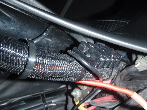 I forgot it was the relay wiring that was in the way of the petcock. Last time I had the tank off I think I decided to move the relay forward, just haven't done it yet. 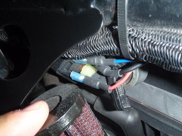 The relay (on both bikes) is powered by the the license plate illumination wire, as suggested by canyon chasers. Here it is on the XB, I just used a crimp on connector (red) for that. 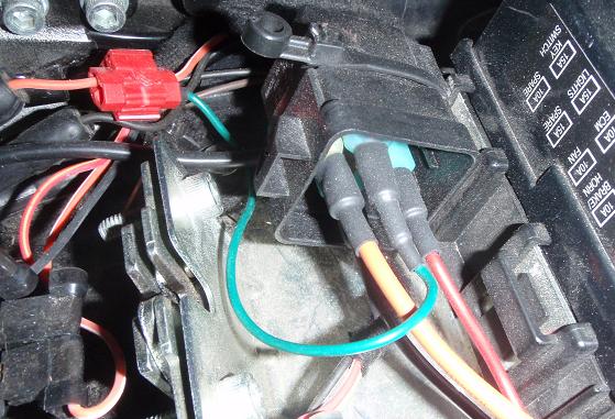 Here's the full wiring under the XB seat. Hopefully it gives some ideas, I was pleased at how cleanly it went in, used small self tapping screws to secure the block to the plastic tray and dabbed black rtv under the tail to conceal the little bit that came through and seal the tray from moisture coming in underneath.  | ||
Littlebuggles |
I didn't find much help on this site, which is why I post so many pics, maybe it will help others who have consdered this but been unsure and put it off. Basically it wires like this, battery to relay for power (relay is switched on by separate power from plate wire), relay to distribution block for your accessories - that's where you'll source your power to the heated grips, vest, gps, radar detector or what-not. The relay, distribution block, spade connectors, and wire came from the local Radio Shack. Larger connectors for the heavy gauge wire (power and neg from battery), and heat shrink sealed connectors came from Auto Zone. I think the inline fuse holder/hot wire came from the Checker/O'Reilly since I liked their part better than the Auto Zone part - it uses a small spade type fuse (10A?), I figured it would give me a backup fuse should I ever need one for regular bike operation, like when the fan fuse burnt out. I hope this is useful. (Message edited by littlebuggles on October 22, 2011) | ||
Harleyelf |
Or you could just go behind the dash and tap your 10 amp in-line-fuse off of the speedometer power wire. The solid state instrument uses less power than a taillight bulb and has heavy enough wire in its feed circuit to absorb some extra load. Up your instrument fuse on the fuse block from 10 to 15 amps and you're ready to go. | ||
Fahren |
Grip heaters don't draw many amps: Polly Heaters, for example, are total 36W (3A); so any circuit that can handle another 3A that is also turned off when the bike turns off is fine. | ||
Littlebuggles |
I like Harleyelf's suggestion, seems a lot cleaner, and easier than all the wiring I ran, and if the standard fuse is good it's even easier. If I hadn't already done it, and having the vest other accessories, I'd do it that way. | ||
Jakenok |
great info here, clear pictures. the distribution block is a great idea, since you can tap into it for some other stuff to olike a GPS, right? | ||
Fahren |
Another easy and totally reversible (maintains existing wiring config.) way to tap into a 12V wire is to use a Posi-Tap. http://www.posi-lock.com/posiplug.html | ||
Xl1200r |
Wow, lots of help here! When it comes to electrical systems, I'm about a 0.5/10, so I had my buddy come over who is a solid 1/10 and we went to work, lol. We ended up doing a few things... 1) I was using the factory heated grip kit from Buell that fits the 1125 and Uly's. It was obvious that the switch was stout enough and we didn't need a relay anywhere. However, the connector for the kill switch and starter button was different between the two bikes, so we cut off the new style and soldered on the old style to hook into the stock S3 wiring harness. 2) The kit itself comes with a harness to connect the switch and each grip, so it was all plug and play from that end. 3) For power, we decided to go behind the fairing. We found a connector with 4 fat red wires right above the headlight - 3 were switched and one was a constant 12v. They looked to come from the ignition switch and go into the main harness of the bike - not sure what they are for but they looked pretty stout so that's what we tapped into. 4) We also went ahead and tapped the cig plug into that as well so it is now switched an not always on. I went for a 400 mile ride yesterday and had no issues, and the grips for some reason work much better on the tuber than they did on my 1125CR. First thing in the morning, probably around 40 degrees and on the interstate I only needed them on the low setting. I will probably go back in over the winter and wire up something cleaner for the GPS which uses the cig plug currently, but it clutters up the dash and also the extra wiring is stored in the left fairing bag. I'm not sure if I'll just disconnect the cig lighter or use the extra accessory plug that was on the grip harness. I'd like to have that cig lighter powered in case I need it for something, but at the same time I'd be weary of running the grips, the GPS AND something else all on that same circuit... | ||
Xl1200r |
BTW - the junction block is a great idea, but the Buell heated grip wiring harness has some of that built in already, insomuch as I have another accessory lead just waiting to be hooked up. I don't run heated gear and can't see needing much else so I'm happy with the options I have right now. | ||
Coxster |
a quick FYI when using relays: the standard 5 pin Bosch style relay has numbers on the pins, and after 25+ years I've never seen any surprises with them. a few 4-terminal relays don't have the 87a. For the Coil: 85 and 86, either can be hot or ground, doesn't matter, but I always make 85 HOT and 86 GND, and keep consistent with this. For the power switching, 30 is the common terminal, either feeding 87a ( think of it as 87ALWAYS) because it's always connected unless you power the coil. The switched output terminal is plain 87. Make sure you have a fuse before the 30 terminal |