| Author | Message | ||
Rickie_d |
Shock bracket with a .250 pie cut which translates to .750 lower rear suspension � Aluminum non-bushed header mount with regulator bridge mount. The regulator is the only module that will be visible on the bike.  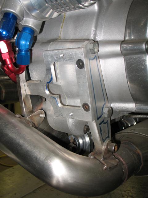 This and all subsequent parts posted are rough outs for mockup & will be further machined for style when all fabrication is complete Custom-built mounts to adapt an XB oil cooler to S&M 2; the anodizing of the fittings will be stripped. 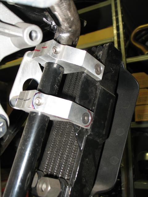  | ||
Capital_g |
Does purchased custom parts count? If so I am proud of this RRC solo tail.  | ||
Rick_a |
This is the last couple items I've put on mine.  I easily could've purchased a digital dash that did all this and more...but I like to keep things simple. The tach has two programmable shift lights which is nice.   | ||
The_italian_job |
hey Mike, you should adjust that seat that doesn't marry very well with the tank cover... that gap it's not suppose to be there. you should call RRC and ask suggestions. mine, which as you know was custom made on a RRC original one, has no gap at all. | ||
Phelan |
Mike, I think you can unbolt the gas tank at the back and slide it back a hair, bolt it back down, and fill that gap. | ||
Capital_g |
Thanks for the tip guys. I noticed the gap before but thought it was something I would have to love with. Never really thought about adjustments. | ||
Ebutch |
Jodie would you post more pics of your Kick-Stand?Also is it leak proof?Buell had one on 1996 S1 briefly,but leakage on primayy resulted I think.  A Green Yard-Glide. (Message edited by ebutch on December 20, 2009) | ||
Ebutch |
Jodie I really like that kick-stand!!!!! also Brake line fitting!!!!!  | ||
Joesbuell |
Thanks for the comments on my side stand, I've done well over 22000klm's with it on the bike and never had an issue with it (and zero oil leaks) Rickie I'd be more concerned about how much you have smoothed the welds on your chassis! But thanks for the tip  My side stand was made while the original one was still in place so that I could get the angles and the foot pad right. It's made from some left over chrome molly 3/4" tube and some 10mm thick steel plate for the main mount on the primary. The pivot on the end of the side stand I turned up on my lathe the notched to fit the primary mount plate. I made new spring mount posts also on my lathe to the same dimensions as the stock Buell ones. I even traced the stock foot as to get the factory look. Sorry for reposting some of the picture's but these are all I took at the time. 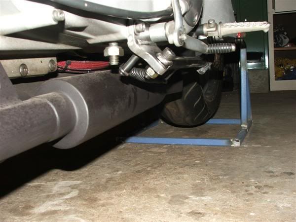 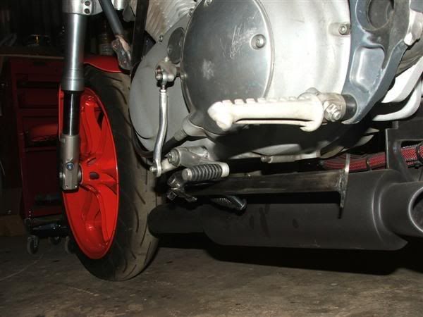 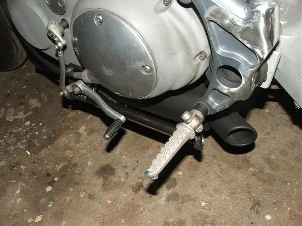 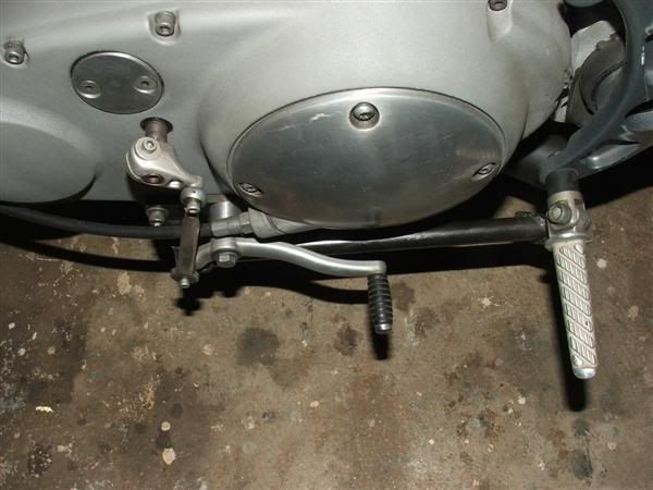  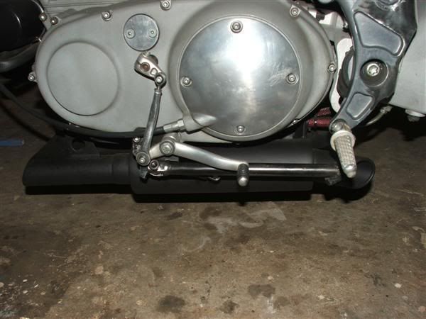 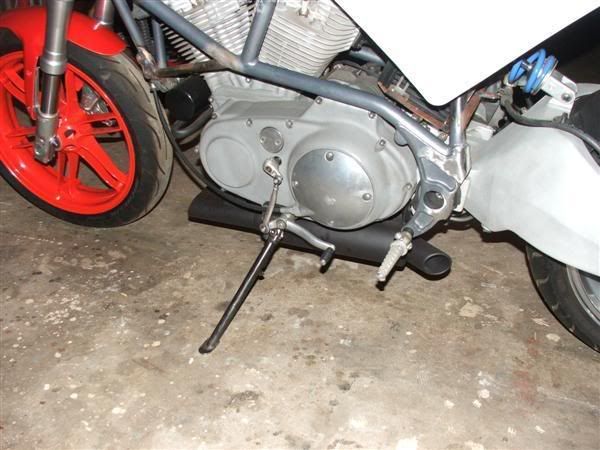 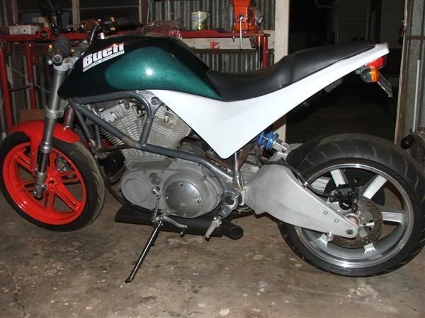 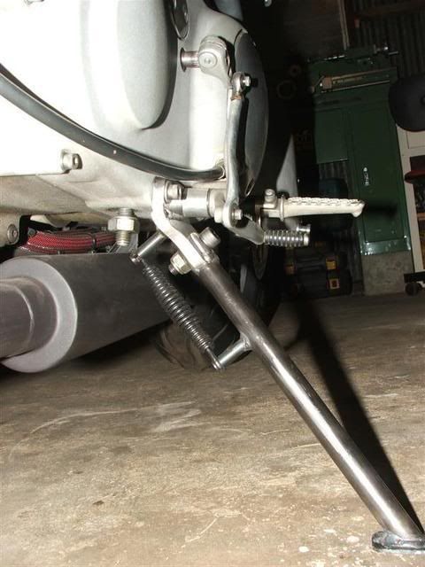   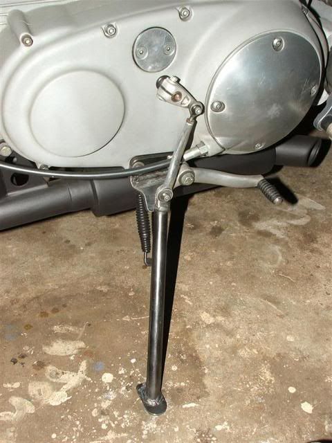  Powder coated and refitted to the bike 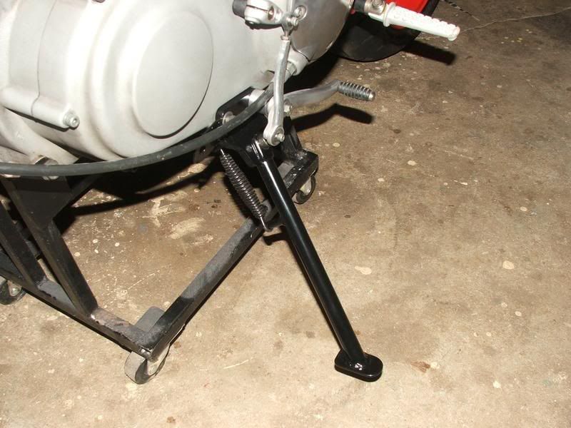 Cheers Jodie | ||
Rickie_d |
Jodie - you are assuming those are factory MIG welds...Not the case! A good weld does not need protruding mass to make the joint strong. (Message edited by Rickie_d on December 21, 2009) | ||
Rickie_d |
Today�s S&M-2 parts are the oil tank and battery box; to make room for an oil tank with some style and an additional quart of capacity, it needed to pass through the vertical frame hoop. The center upright post was removed along with all brackets and upright battery box. I formed a new horizontal battery saddle directly on top of the frame spreader brace. All this cleared way for the rubber mounted, baffled, 3.75-quart tank.    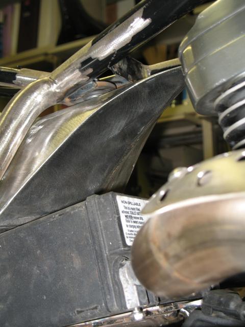 Then I machined a battery hold down & posts (not done). 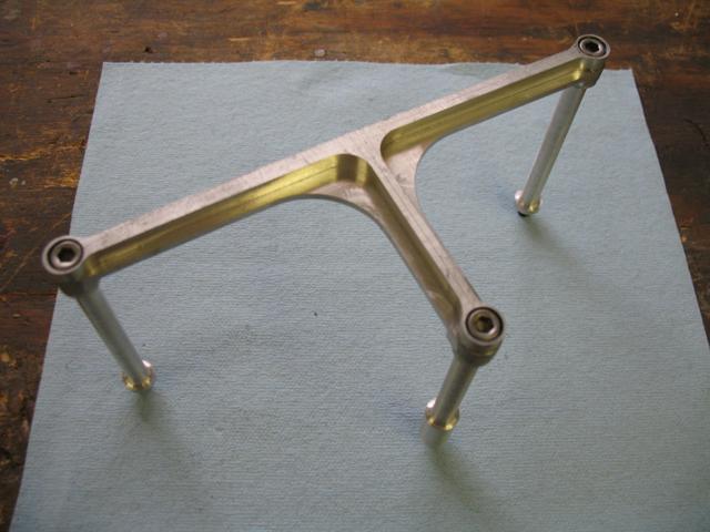  | ||
Ebutch |
Jodie      (Message edited by ebutch on December 21, 2009) | ||
Phelan |
Rickie, how bout some pics of that header??? | ||
Blazin_buell |
Purpony, that is the stock shift lever. I cut off the short side and used the longer side upside down then a short adjustable shaft and I used a bigger (don't remember what year)shift shaft clamp so I could use a bigger bolt to attach to the rod. Broke a couple of those bolts before figuring out that the X-1's had a larger surface area where the bolt threads in. Rick and Jodie, I wish I had some of tools you two have to play with, I could really go to town carving some stuff up for her then. | ||
Ebutch |
SHANE YOU HAVE THE TOOL.CARVE SOME CORNERS WITH IT.  | ||
Rickie_d |
Ross � the header was four parts down on my list, but since you asked I�ll moved it to the front of the line. The header was built by Doug Cook of ARC fabrication. I was studying header designs and considering building my own based on recommendations from an engine builder. Then I stumbled upon his candidate to replace my �Kooks curb feeler�. Doug is big into Ducati�s and took a shot at building headers for Buell�s back in 2005. He was very secretive about the specifications and actual performance, but I gave it a shot anyway since it was not that expensive, relatively speaking. When I got it I immediately saw some short comings such as no front mount and uneven seating of the primaries in the collector. So I fabricated a shoe for the front mount and evened up the primaries to seat correctly, but the pipe still broke in several places. I sent it back, and Doug added another slip joint and retaining spring to the front primary. I repaired the rear primary and added the heat shield as it cooked my leathers, then solid mounted the system and have had no problems since. He had a nice slim stainless muffler that had too much bark for me so I have adapted a V&H unit for now as it has a little more volume and mellower tone. I never dynoed it as it has not been run on the engine it is intended for yet.   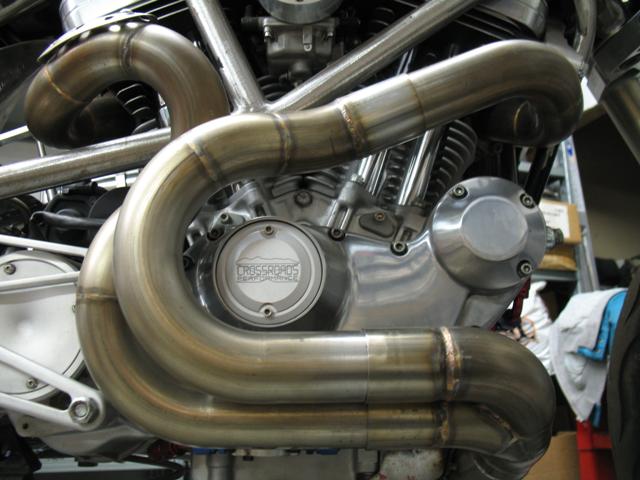  By the way, I fabricated two front mounts on this application. (Message edited by Rickie_d on December 22, 2009) | ||
Phelan |
That header is sick. I had a similar idea in my head for one a while back, but funds didn't allow at the time. I ended up with a Force exhaust (one of my favorites). | ||
Rickie_d |
On the S&M frame I wanted to lower the angle of the sub frame and widen it to accept my modified S2 bodies then build a custom tail mated to a modified S2 tank cover. To accomplish this I made a sub-frame fixture from my stock S2 frame, cut the M2 sub-frame off, and bolted up the fixture. The electrical component brackets have been removed from the seat support area to move the support struts up at a steeper angel to conceal them more. A rear oil tank support was built in the sub-frame. All the 02 M2 components and brackets electrics (fuse/relays, Ignition module, and bank angle sensor) have been moved under the fuel cell. Due to the variations of each S2 body, I made my front fuel cell cover brackets as �sub� assemblies. Fabricating each set of intermediate brackets for each body to mate with the frame bosses prevents stressing of the glass body work. The choke cable has been moved to a different location on the upper stabilizer mount and the ignition moved to the frame.        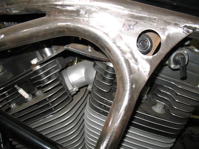 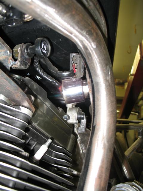 | ||
Rickie_d |
I used a Works shock; however the remote reservoir is mounted reverse from the common manner with AL2 clamps I made as opposed to the hose clamps provided. This allowed the reservoir hose routing behind the primary (with the clutch line) as opposed to the gangly loop in front of the engine. It is nice and clean looking from the front. It is a little more difficult to R&R the shock for service, but it looks much better and it is not like service is that frequent.    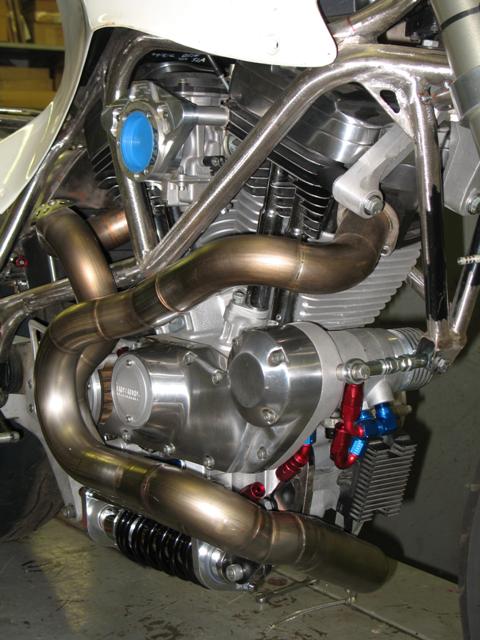 | ||
1313 |
Rickie, Your bikes are always works of art! And I think that it's awesome that they are usually based around the S2. I can't wait until we all see the finished product of this build! Where's that popcorn-munching clip art? 1313 | ||
Easyrider |
Rickie my compliments.. | ||
Rickie_d |
Brankin - This version is going to be a departure from the last three. I will be starting from scratch with the faring and tail section styled to fit in with the lines of a slimmed down S2 tank cover. The tail will still have vents but a reshaped integrated R1 taillight. The faring will be much flatter with a cut down XB wind screen; a true bikini with a top & bottom, but nothing in-between. I will get back to the project when I get off these crutches in a month or so. (Message edited by Rickie_d on December 23, 2009) (Message edited by Rickie_d on December 23, 2009) | ||
Rickie_d |
Thanks Brinnutz & Easyrider � Here are a couple more installments. I fabricated the rear sets; they are adjustable in two �� increments vertically with two shift lever ratios. They are mounted on sealed bearings for smooth action and to reduce slop. The first three images are where I was playing with lever ratios and linkage routing.  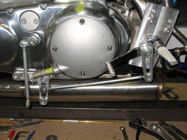  Then worked on the actual look of the levers. 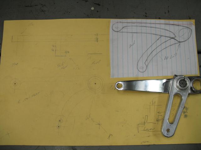  Then setup and machining...   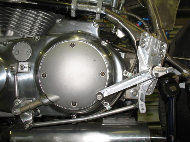  Like all the machined parts on this project, they are not finished yet, just functional and close. That way I can drop and ding them before they are actually done. | ||
Rickie_d |
These axel adjusters I made to be utilized on a custom built swing arm; they incorporate a treaded left adjuster that eliminates the axel nut and covered by sliders. 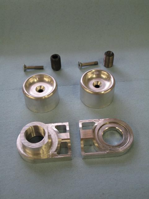  Here are the fronts�  And the bar ends machined to match�  (Message edited by Rickie_d on December 23, 2009) | ||
Rickie_d |
I will build the swing arm next, here is the jig coming together using an aluminum swing arm.  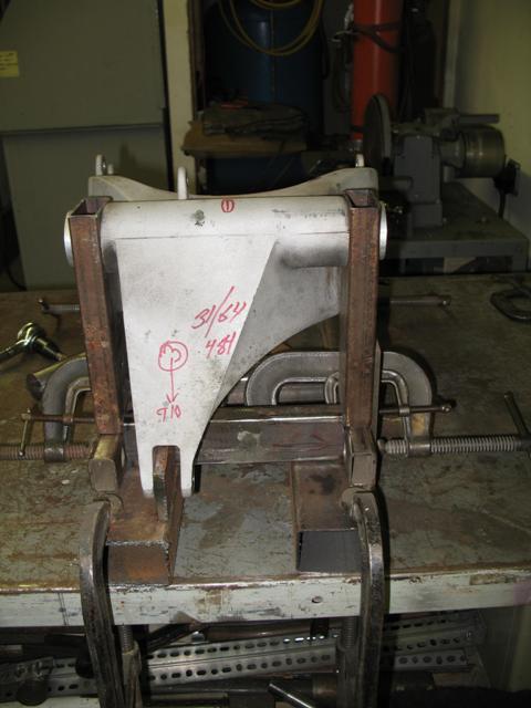  When finished the jig was checked against another AL-2, then steel swing arms, they all slipped in and locked down perfectly The swing arm pivot with shock arm have been stripped from a steel donor and mounted in the finished jig. I am now working on designing the AL-2 axel blocks. When I finish machining the blocks they will be mounted in the jig and I start to �connect the dots� with chrome moly tubing. 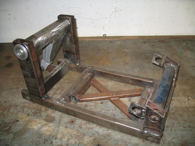 The result will be a trellis style on the same lines as this Bimota unit.   | ||
Benm2 |
Rick:  And your machining these parts on a vertical mill with a rotary table? Do you at least have DRO's? | ||
Rickie_d |
Ben - Correct! I never invested in DRO's for my lathe or mill. I often say to myself...Rick...because that's my name. You really should make it easier on yourself & cough up a few bucks for DRO's on these things. The problem is I never seem to answer myself and just muddle along. I was just putting together my post on the gauge pod...this one will get you going!!! | ||
Rickie_d |
For gauges, I drafted plans to machine a housing that loads from behind a dash panel in the faring. It utilizes a modified Buell analog tachometer, Dakota Digital speedometer with back lit indicators, and Dyna shift light. The tach body, face, and internal electrics had to be removed or altered to get cozy with the speedo internals. 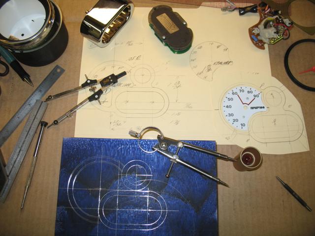 This was a little complex when it is all manually machined; no CNC or even a DRO was used. I machine the face (blue) to a given depth, then flip it over and blindly machine the gauge cavity (red) to depth and in alignment with the face. I was not totally blind�I had some measurements written down, my �minds eye�, and a few index holes to reference.      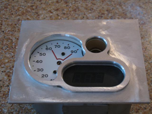 Pinning and tinning in the individual components�  I could have just purchased a gauge package from someone, but most did not have the appropriate scales I wanted. Also, what fun would it be if there were no headaches involved? | ||
Skntpig |
Speechless... | ||
Brinnutz |
^ + I want some. lol |