| Author | Message | ||
Gowindward |
Here are the parts needed. Using original S3T rotor and main shaft sprocket. 1 x Y1302.02A8 $64.80 XB Voltage Regulator 1 x 29971-02YA $113.60 XB 38 Amp 3 Phase Stator 1 x 72614-01BK $6.40 Terminal Socket For Stator 1 x 72654-01 $0.40 Socket Lock Wedge for above socket 3 ft 10 AWG wire red 3 ft 10 AWG wire black Wire sleeves-- Expandable Mesh Sleeving 1/4" ID, 1/8" to 7/16" Bundle Dia, 10'L, Black --Item #9284K412 at Mcmaster.com (Used on new wire from VR connection to ground and Main circuit breaker.) EASY-OPEN POLYESTER WRAP-AROUND SLEEVING, BRAIDED, 1/8" ID, 1/16" TO 1/8" BUNDLE DIA, 3' Long--Item #1459T11 at Mcmaster.com (Used to cover oil pressure sending unit wire) 1) 3/8" x 4" x 5" aluminum plate used for voltage regulator adapter mounting plate. Source Mcmaster.com 2) 1/4-20 x 3/4" flat head socket head cap screws-stainless steel. Used to mount VR adapter plate. 3) 10-24 socket head cap screws - stainless steel used for mounting VR to adapter plate. Parts on order are some of the wire plug/ connectors used on the XB's that are different than my '02 S3T. The details hold you up every time! I'll have a list of those once they come in and I figure out what exactly is needed. I ordered a rotor because I could not confirm whether it would be needed or not with knowing that at the minimum the sprockets would have to be swapped. The good news is the rotors are dimensional the same except for the sprockets. I'm using my original rotor, but photos below show the two rotors side by side. The XB part is on the LEFT in each photo. Besides the sprocket tooth count being different the XB hub on the inside of the rotor is also about .100" shorter. 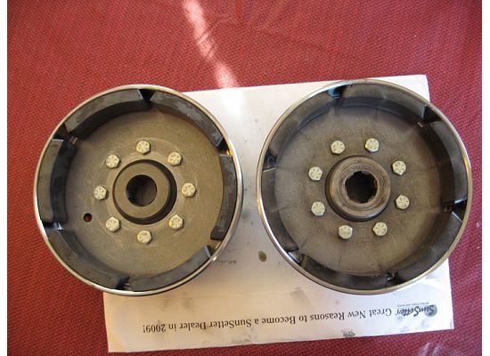 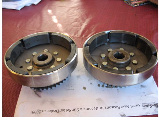 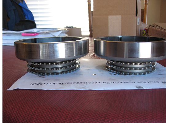 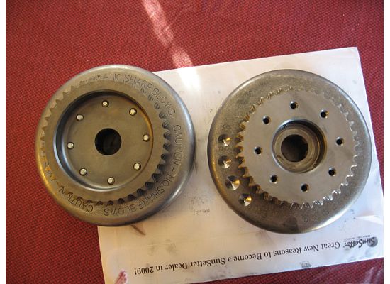 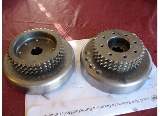 Here are photos of the stators. Again the XB parts is on the LEFT. As you can see the XB stator has 18 coils on the circumference versus 12 coils on the S3T. The thickest part of each stator is right at 1" on both parts and the O.D.'s and I.D.'s are equal. The one dimensional concern is the center hub is about .100" thicker on the XB stator. Hmm...Is this going to be my down fall on the project??? 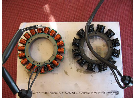 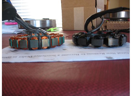 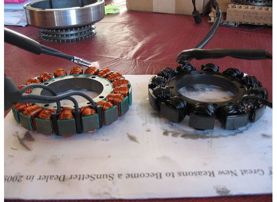 Okay here is the stator bolted in and ready to check fit with the S3T rotor. 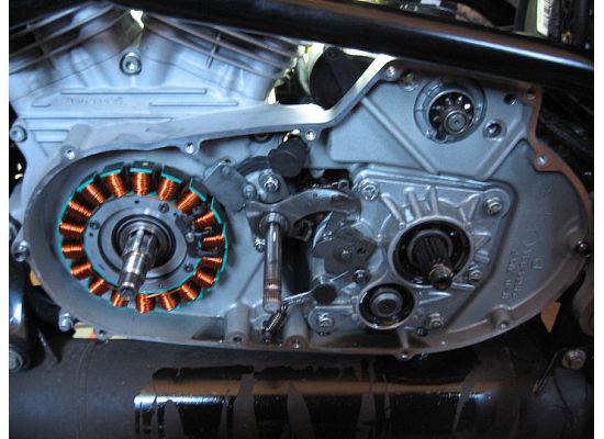 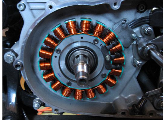 Okay it's not genuine Silly Putty, but it's what the dollar store down the street had. 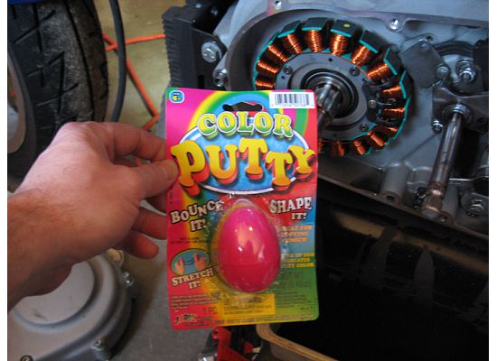 Placed some Silly Putty in the most likely places of interference and then install the rotor and see how thin it gets smashed. 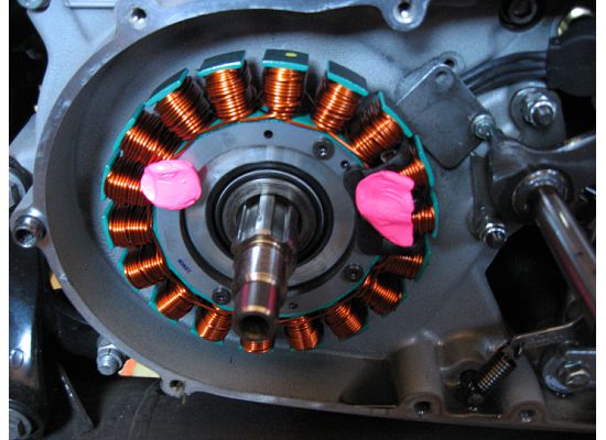 Here's after the rotor was installed and removed. It looks pretty good! 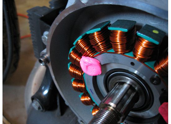 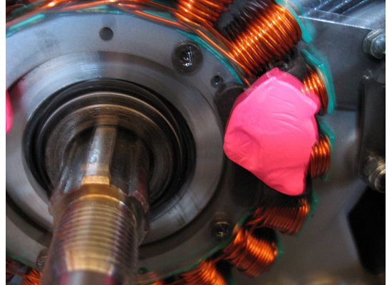 Smashed thin, but still enough clearance to move forward. 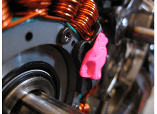 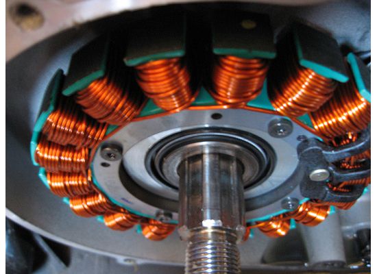 One more putty clearance check on the stator attachment bolts and the rivet head that holds the plastic insulator onto the stator. Again the results are good. 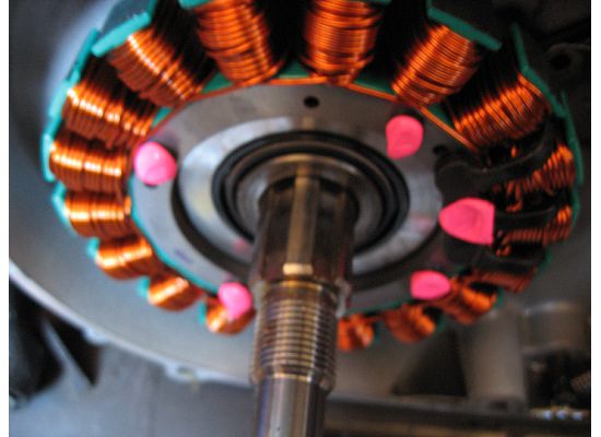 At this point I have the rotor, clutch basket and primary chain installed and waiting on electrical connectors that I ordered yesterday. I have a new XB voltage regulator in transit (it was on backorder for 3 months!) and should be here Thursday.  I'll post up final details on the electrical connects when I get the parts in hand. It looks simple enough once I have the parts, although dissecting the wire harness will be tedious. I'll post up final details on the electrical connects when I get the parts in hand. It looks simple enough once I have the parts, although dissecting the wire harness will be tedious. (Message edited by gowindward on February 01, 2009) | ||
Henrik |
Loren; that's an outstanding initiative. Talk about diving in ... So after all my agonizing over this over a year ago, the stock rotor will work fine. That figures  Of course, I got a fresh stator installed during BRATPAC II last year, so upgrading has moved down the priority list a bit  Great work so far. Keep us posted with outcome and final parts list, wiring trouble etc. Thanks for sharing Henrik | ||
Phelan |
I'm looking forward to the progress here as well. My only question is why not use the 45 amp system that was in the Ulys for a couple years? | ||
Gowindward |
"My only question is why not use the 45 amp system that was in the Ulys for a couple years?" Well....Now you tell me! Actually I'm pretty sure the Uly came out with the same 38 amp 3 phase system as the other XB's. (I'm using my '04 XB12R service and parts manuals as my road map) and all have gone to a 30 amp single phase system. The S3 had a 22 amp single phase on it. To get to 45 amp you would be looking at a H-D big twin charging system, which from photos online of those stators, they would not fit. (Message edited by gowindward on January 21, 2009) | ||
Phelan |
IC. Maybe I read wrong. Anyway great job. I hope to be doing a similar upgrade some day. | ||
Fasted |
iwannadoittoo!! glad there is always someone knows what to do, how to do it, and willing to share!! gotta love our forum. keep the info and pix comin', please | ||
Texastechx1 |
this thread is now bookmarked on my computer THANK YOU! | ||
Bad_karma |
Loren Great project and documentation. I have consider this for awhile now. Will be watching and waiting for the final report. Joe | ||
Skntpig |
Watching this myself. Am I correct in assuming that you only need a stator and regulator and the associated connectors to make this work? Keep us posted. THANKS AGAIN! | ||
Gowindward |
"Am I correct in assuming that you only need a stator and regulator and the associated connectors to make this work?" Pretty much that is correct. I'm installing a new primary gasket as leak prevention, (old looked okay) and I fabricated my own sprocket locking link to lock up the primary, so the nuts could be broke loose and tightened. I also had to buy a 250 ft-lb torque wrench and a deep well socket to tighten the main shaft rotor nut to spec. Oh and a cool pair of Craftsman snap ring pliers. The one I had just didn't open wide enough to remove the big snap ring on the clutch basket. When I get it all wrapped up I'll post up a final parts list, and wiring details. | ||
Oldog |
Actually I'm pretty sure the Uly came out with the same 38 amp 3 phase system as the other XB's. (I'm using my '04 XB12R service and parts manuals as my road map) and all have gone to a 30 amp single phase system. This makes me wonder Why the 3 phase system was dropped, Just cost or were there issues with the regulator? it seems like a good idea to me, using 3 phase and rectifying it to DC would seem to me to give less ripple to the output. Great up grade none the less, is the XB crank sprocket and magnet assembley lighter? | ||
Gowindward |
I think they had problems with both the stators and the voltage regulators. Here are photos of an earlier version of an XB stator. Notice the potting compound where the three strands of wire exit the stator. That has been replaced on the newer stator I'm using with a molded plastic piece and some insulating sleeves. The voltage regulator p/n was also rolled near the time I placed my parts order in Oct. and I had to wait three months for it's delivery. That must have been do to some design or manufacturing changes. 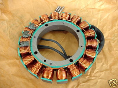 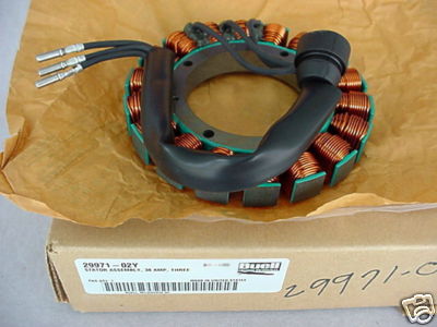 So not only am I getting more amps, but I'm getting the latest and greatest components! Not sure on the rotor being lighter. I didn't weigh them. The magnets an hub they are mounted in are the same dimensionally, while you can see the XB sprocket does look like they took some material out of the center. | ||
Skntpig |
You're not using the xb rotor are you? | ||
Gowindward |
"You're not using the xb rotor are you?" No, I'm using the original S3 rotor and sprocket. New XB voltage regulator temporarily mounted waiting on material to fab an adapter mounting plate. 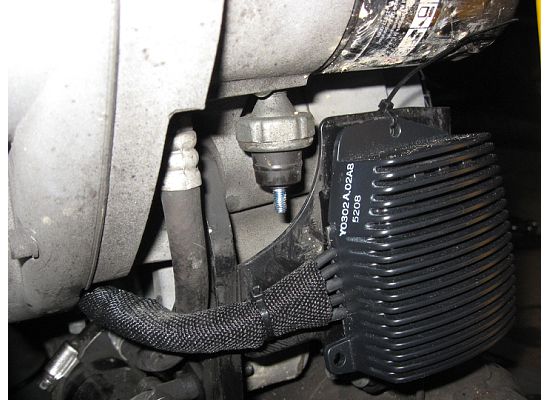 VR wires routed up under and behind the side cover. 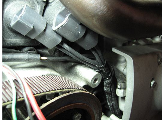 Showing VR wires up under the side cover. 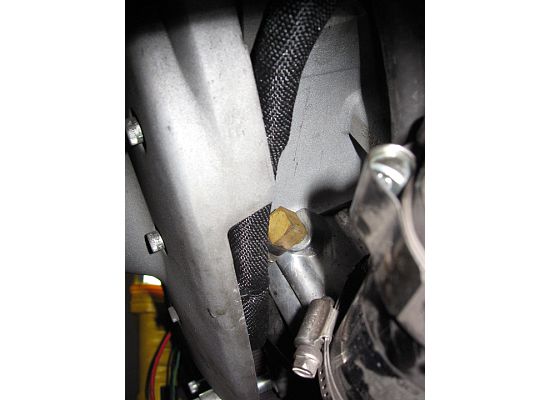 These socket components came with the new VR. The terminals are attached to new 10 guage wire. 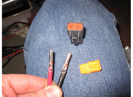 See the "1" & "2" on the socket. Those are used on the wire diagrams to indicated Pos & Neg. 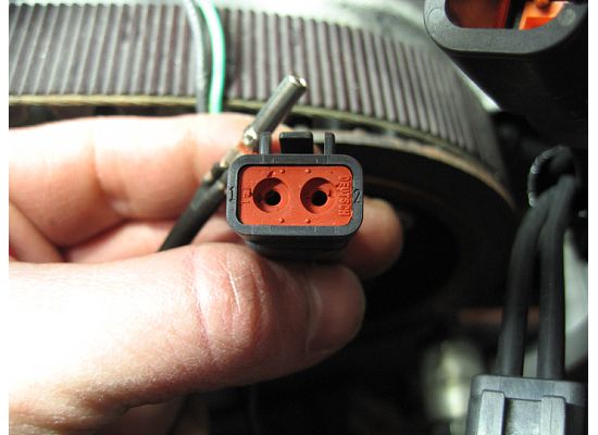 Here stuck waiting on some wire sleeve the route the positive wire up to the main circuit break and the negative to the main ground. 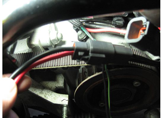 Here waiting on the socket and lock for the stator terminals. 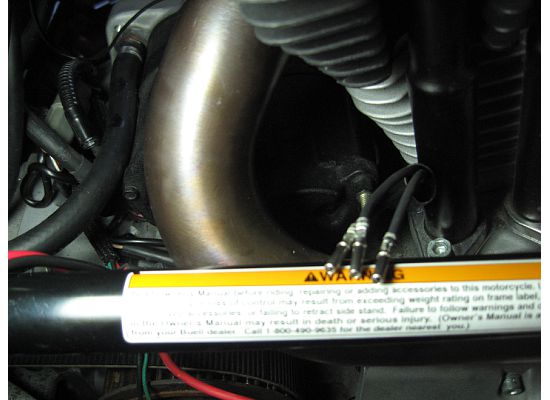 Now waiting on the UPS man to show up Tuesday with parts.  | ||
Gowindward |
I finished up the wiring last night. Arrows point to the new wiring. I ran new wire from the VR connection up the the main circuit breaker and the main ground. I ordered wire sleeves from Mcmaster.com to make it all look real clean. 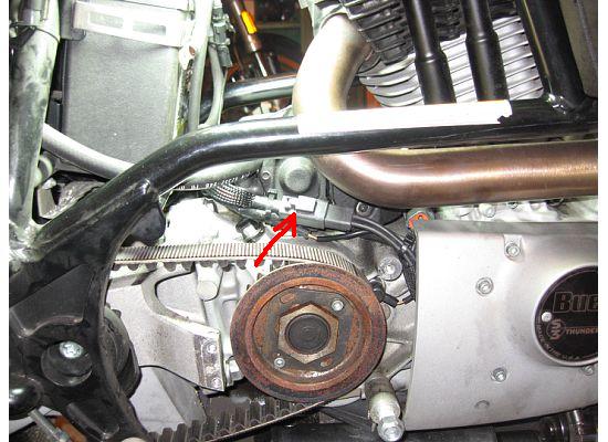 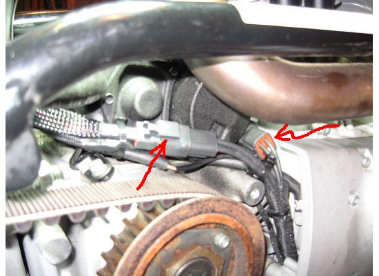 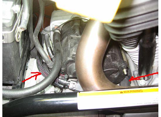 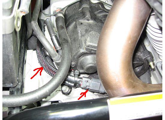 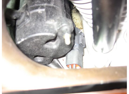 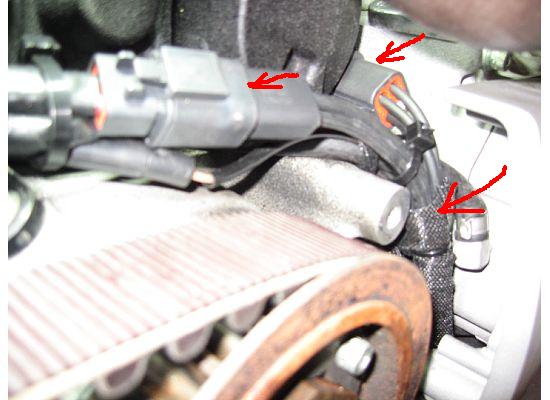 Here is the start of the adapter mounting plate for the XB VR. Cross hair locations are the old VR mounting locations and will use them to mount the plate to the original mounting bracket on the bike. Three dot locations will be drilled and tapped for mounting the XB VR. 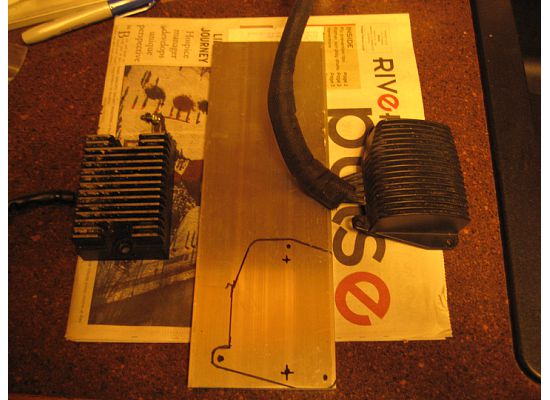 | ||
Sleez |
very cool, keep up the work. | ||
Bad_karma |
Great info Loren, how much bigger is the 3 phase regulator than the single? Did I understand you correctly, both the male and female two wire plugs (DC) come with the Voltage regulator? Are the splines on the XB sprocket the same as the S3's?(crankshaft) Thanks Joe (Message edited by bad_karma on January 30, 2009) (Message edited by bad_karma on January 30, 2009) | ||
Gowindward |
Joe, the two voltage regulators are shown in the photo above. The XB VR is on the right in the photo. The photo shows the start of a mounting adapter plate for the VR. I'll show more of it this weekend after it's completed. "Did I understand you correctly, both the male and female two wire plugs (DC) come with the Voltage regulator?" Yes, both the male and female connectors/ plugs came with the XB voltage regulator. "Are the splines on the XB sprocket the same as the S3's?(crankshaft)" I think they are, but I didn't try fitting the XB sprocket to the bike since I measured some hub depth difference that I knew would cause a fit problem with the stator. I'm using the S3 rotor and sprocket. | ||
Bad_karma |
Thanks Loren, looking at the pictures of the voltage regulator doesn't look too thick for my mounting location. Thanks for the information. Joe | ||
Skntpig |
Bravo man! Great right up and pictures. Thanks for taking on the project and keeping us informed. Now I have to decide if this is necessary on my S1 if I plan on never running any extra electric accessories. | ||
Gowindward |
Here's the voltage regulator mounting adapter plate after fabrication and before paint. I used a band saw, disc sander and hand drill for the fab work. 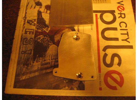 Oops! Needed a little clearance for some screws on the back of the VR. The die grinder...although crude, but gets the job done. 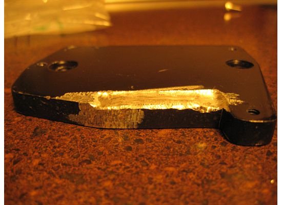 Here the stock mounting plate before adapter plate installation. 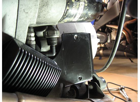 Adapter plate installed. 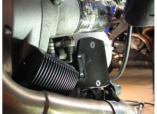 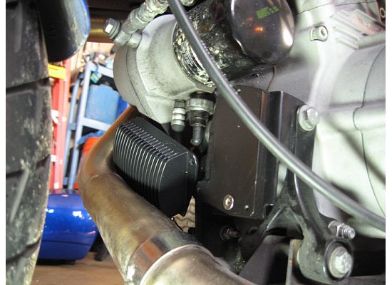 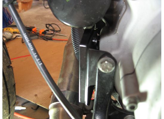 Here's the new XB VR installed. This the last of the work except for installing the tail body work I pulled off to get access to the wiring around the battery. 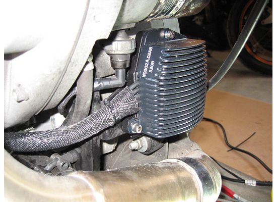 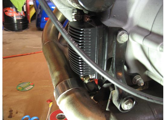 Then fire it up and  It's NOT CHARGING!!!! Oh Crap!!! Okay time to back track and figure out what I screwed up!! Okay so I spent a few hours troubling shooting the new charging system All the wiring checks out...Stator output volt checks out. Hmm...No it couldn't be the brand new voltage regulator???? I had a second VR that I purchased off ebay, but was used. I guess I'll wire it up and see if it works. Sure enough the used VR works and the system is charging. So I removed the new VR and installed the used one and put everything back together. It's NOT CHARGING!!!! Oh Crap!!! Okay time to back track and figure out what I screwed up!! Okay so I spent a few hours troubling shooting the new charging system All the wiring checks out...Stator output volt checks out. Hmm...No it couldn't be the brand new voltage regulator???? I had a second VR that I purchased off ebay, but was used. I guess I'll wire it up and see if it works. Sure enough the used VR works and the system is charging. So I removed the new VR and installed the used one and put everything back together. Here's the icing on the cake!!! My new voltmeter showing the now Super Charged S3T!! 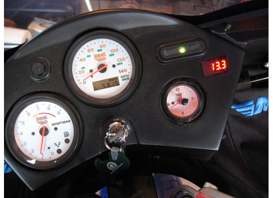 | ||
Natexlh1000 |
whoo! You the man. | ||
Xldevil |
Thank you for that perfect report!!!!!!!! Ralph | ||
Texastechx1 |
what an awesome write up... LOVE IT! | ||
Bad_karma |
Great job and timing, I ordered the parts today, soon I can get my primary back together. Joe | ||
Xldevil |
What´s the difference between VR Y1302.02A8 and Y0302.02A8 I found both numbers,but it seems like these parts are equal. Ralph | ||
Gowindward |
Thanks guys! It's been a good project. Ralph, The Y1302.02A8 part is an updated part and the external difference is the socket on the DC (outlet side) of the VR. Y1302.02A8 is a kit with the VR with terminal sockets installed and a kit of sockets & terminals for the DC connection to the bike, which was good because I needed them for the conversion. See image below for the parts. 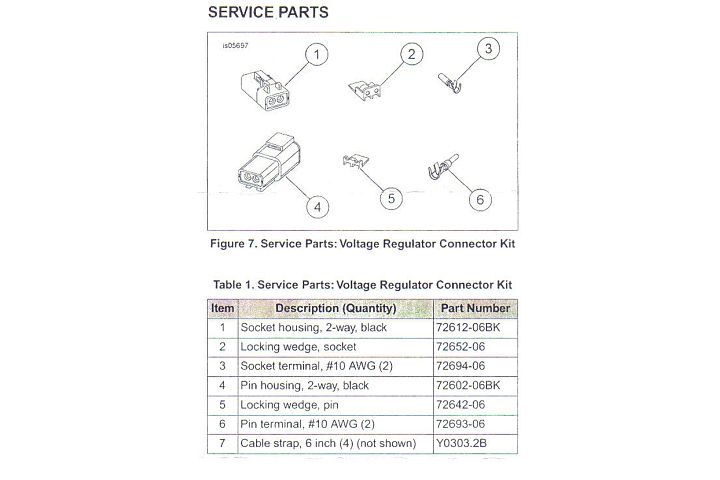 These are different than what's on my '04 XB12R. These replace the infamous "77" connector that had a number of problem discussions on the Uly board. | ||
Sleez |
so, did you get a bad new VR, or was it the wrong type? bad connection? great write up, thanks. | ||
Gowindward |
I think it was a bad VR. I triple checked connections...etc. When I plugged in the used VR everything worked. Swapped back to the new VR, and again no charging. So, I'm real sure it's a defective new VR. Hopefully the dealer will exchange it. | ||
Xldevil |
The Y1302.02A8 part is an updated part and the external difference is the socket on the DC (outlet side) of the VR. Y1302.02A8 is a kit with the VR with terminal sockets installed and a kit of sockets & terminals for the DC connection to the bike, I´m not quite sure if I got that right,you know I´m no native speaker. Y1302.02A8 is a kit with the VR with terminal sockets installed and a kit of sockets & terminals for the DC connection to the bike,as you wrote. Y0302.02A8 is singly the VR. Is that correct? Ralph |