| Author | Message | ||
Aaomy |
ok guys so hears the next thing you ask for. ok i started with bone stock xb9 heads,, 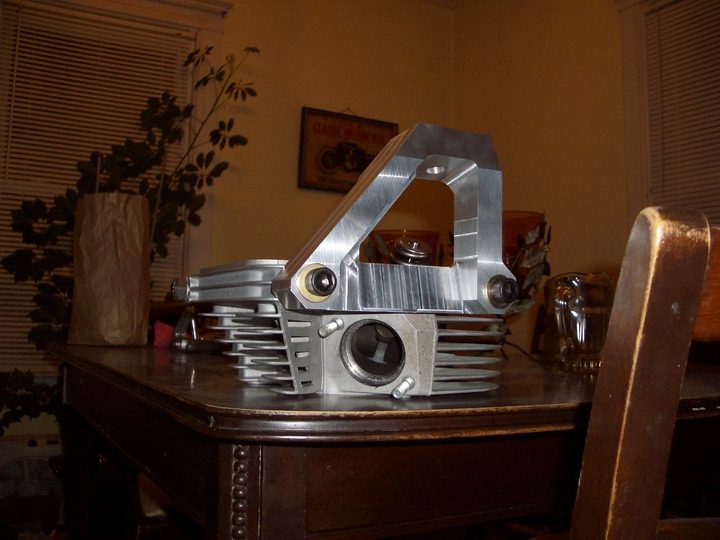 i will go into the set up on them in another thread. xb heads "among other differences" do not come with taped breather holes! xbs breath threw the upper rocker cover and have the manifold pointing up between the cylinders. to place these on my s2 . i first needed to cut the the bosses where the breathers normally exit the head to the correct height. this will allow the carb to mount to the proper depth. second that hole has to be taped 1/2x13. this is where my heads slightly vary away from the norm.. 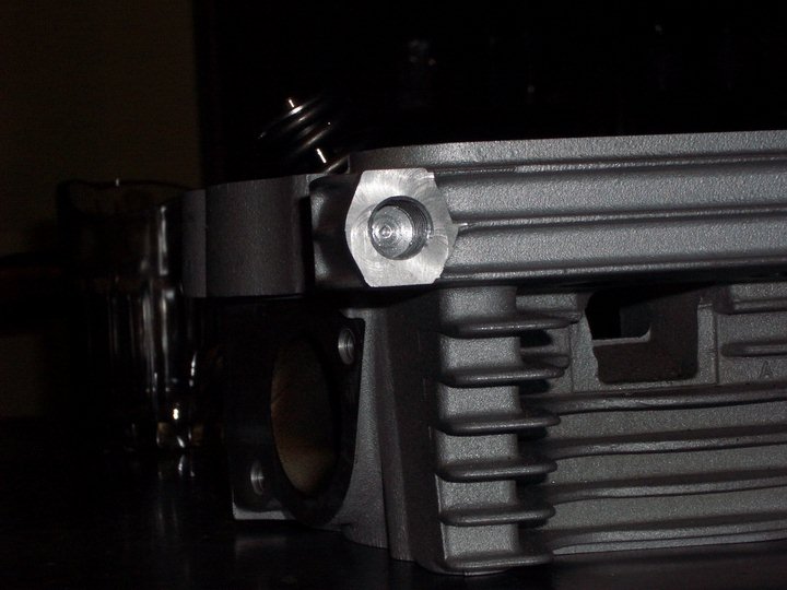 | ||
Aaomy |
i still wanted to use my existing three piece rocker covers. silly me. xb heads have the same pin hole that the lightening and thunderstorm heads breath threw. normally that taped hole would break threw into the pin hole allowing the soiled air mixture to exit the engine. on mine i did not drill deep enough to break threw into this "pin hole".. pin hole meaning dowel pin hole. 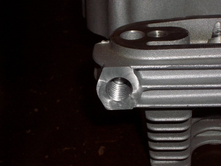 in the picture you can see the dowel pin hole above the taped hole. instead of breathing out the front of the engine and into the cab "mouth breather".. i wanted my breather to exit the rear of the heads. or at least exit in that direction. i did this by drilling into the rear of the boss and into the pin hole. i drilled this for an 1/8" pipe tap. 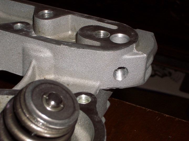 | ||
Nitsebes |
Is that the stock xb isolator mount? looks billet.nice pics btw | ||
Aaomy |
nope thats another one of my little projects. i will go into that project next if you guys want.. on my other thread i started taking request on the order of posting projects. let the s2 projects begin! please go chime in either here of there if you wish. thanks aaron | ||
Aaomy |
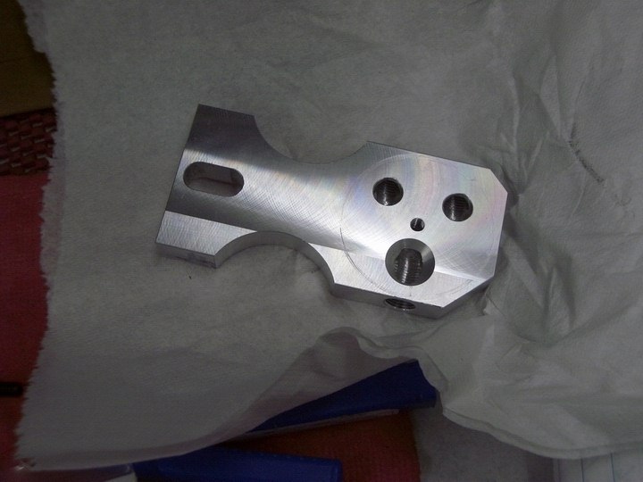
ok so this picture just kinda shows you whats going on so far. the barbed fitting isnt the one im going to use. its just their as an example. 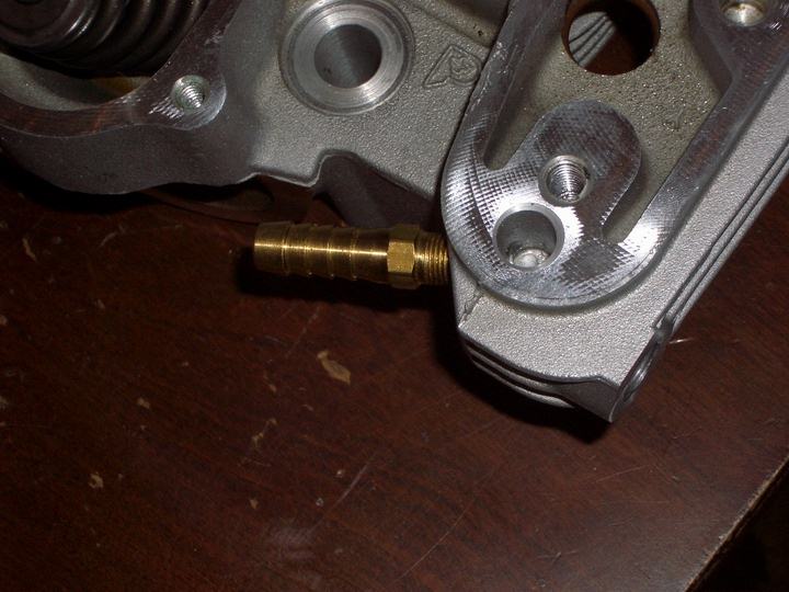 if you wanted to try this it would work on any heads if you just replace you breather bolt with a solid one. you probably would want to use some kind of thread sealant. even teflon tape might work just fine. | ||
Aaomy |
so hear is the fitting i chose to use. it is an 1/8" npt to 3/8" copper tubing fitting, like most my projects just pick them up at your local hardware store. i purchased some 3/8" al tubing to use as my air line. 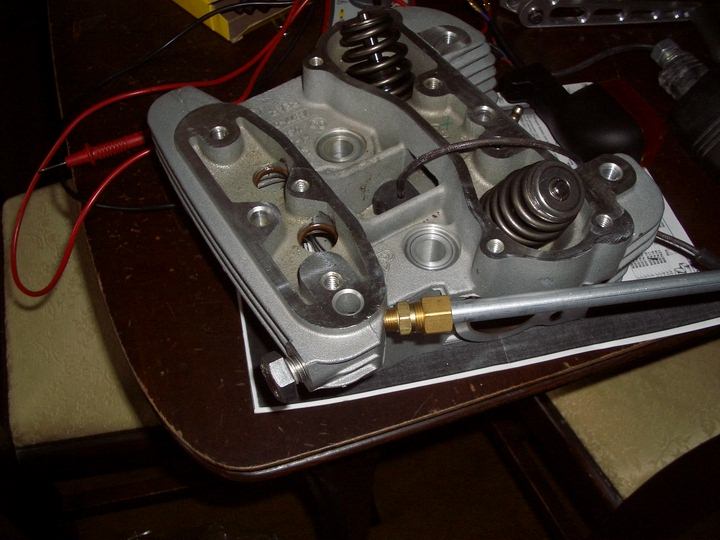 this picture is of the rear cylinder head. you can see the bolt hole where the top motor mount attaches. on the xb heads there is a extra bolt hole directly across the spark plug from it. on my tuber this is of no use "sort of".. so i decided that they chose to put that their so i had a convenient place to mount my catch can!! | ||
Rek |
You must not be married, Aaomy. LOL. My wife would throw a hissy-fit if I started bring projects into the dining room! Rob (nice job, BTW) | ||
Djkaplan |
Do you think a 1/8" fitting is going to be a bit restrictive? | ||
Aaomy |
djkaplan, the 1/8" npt fittings have over 1/4" clearance threw the middle along with my choice of tubing . the stock tubing fittings are more restrictive. much less those 1/4" od over or under banjo bolt breather re routing kits. look threw a stock banjo bolt that most replace theres with and youll see holes and passages probably less than and 1/8". nope, not worried about the restrictiveness of this system,, pre drill for and 1/8 npt taped hole is a letter R drill, .339", dont really know why the call it and 1/8", its actually closer to 3/8". hope this helps clarify. | ||
Aaomy |
rek,, yup you nailed that one on the head.. this is a mid project dinning room, parts also located in the bed room, computer room, and basement.  just me and the rabbit,, and the rabbit dosent mind. | ||
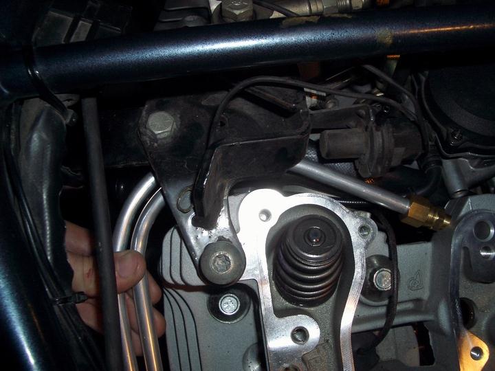
Aaomy |
so now that you did all your xb head preping (ill cover that in a different post) properly install the heads, intake manifold, carb, and set on the top motor mount.now you can start routing your tubing. 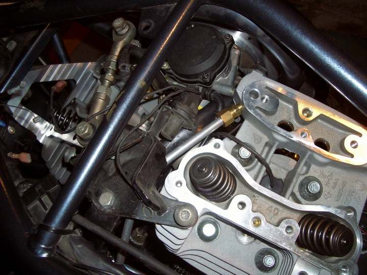 you can now start to see that this is a tight fit. on the rear head you have to guide comfortably around the fuel line and enricher cable. on the front head you are very close to the throttle control wheel. 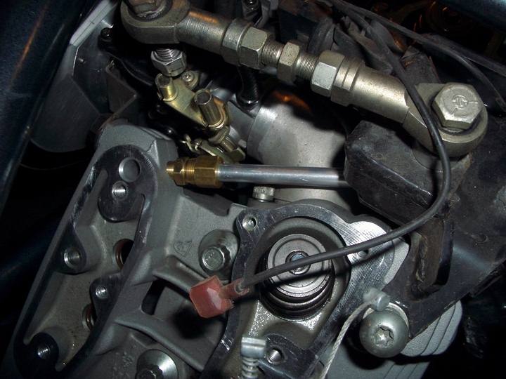 | ||
Aaomy |
 here i carefully started to bend and route the al tubing around and back to where the catch can will be installed. 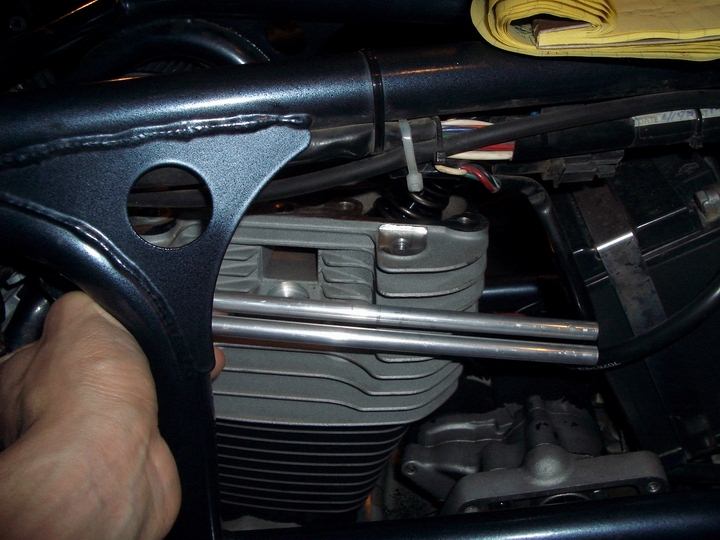 here is where the tubing will end and the bolt hole on the rear head where the can will be attached. | ||
Aaomy |
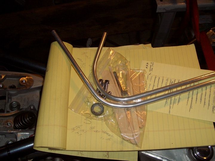 ok so here is what the bent tubing looks like. at this point i started on the catch can. currently i have to shuffle off to buffalo, seriously. when i get back ill start posting pictures of the catch can | ||
Phat_j |
just out of curiousity, why hard tubing rather than hose....... one concern is that the motor is rubber mounted and jumps all over the place... if your catch can is mounted to the frame (which most are) then the tubing becomes the flex point... maybe i'm wrong.. | ||
Aaomy |
my catch can is mounted to the rear head. check a couple posts above and youll see where. it jumps with the motor.. no worries on the hard tube flexing other than very slight heat expansion. and the al grows with the al. like metals ,, like expansion rates,, i like it.. | ||
Phat_j |
you've definatly put alot of thought into this.... good for u... | ||
Djkaplan |
"pre drill for and 1/8 npt taped hole is a letter R drill, .339", dont really know why the call it and 1/8", its actually closer to 3/8". hope this helps clarify." It's because the fitting has NPT threads. Pipe size is the accepted industry designation, not the actual measured size. 1/8" NPT fittings are about 3/8" OD diameter and just a little larger than 1/8" ID. | ||
Aaomy |
actually most inside diameters are larger, closer to 1/4". the smallest i measures was .190 on a 1/8 to 10-32 conversion . and thin wall fittings come stock around .269 internal. you can also enlarge them safely for low pressure applications out to .320 id. the fittings and the pipe are both purchased by wall thickness. this varies on fittings and applications due to pressures and flow requirements. i usually clean up the inside of any fitting going onto my bike, i lightly cut the insides and chamfer any leading edges to promote best possible flow. ok,, now back form buffalo lets begin again. so here i started with 2" 6061 al, the chunk im using is probably 2.25 long. i lightly dress the outside and drill a 1"hole down the center 1.75 deep. 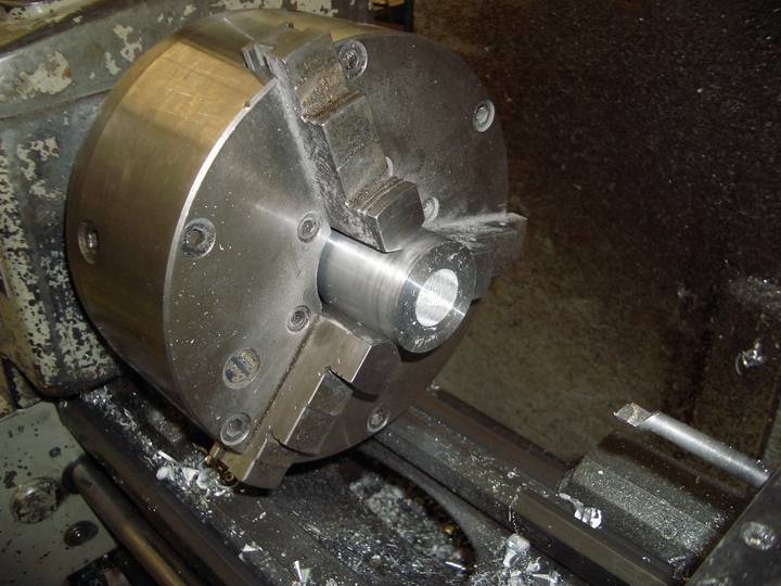 | ||
Aaomy |
i then use a boring tool to enlarge the hole out to what ever measurement makes you happy. another words. leave enough meat to decorate the outside how ever you see fit. 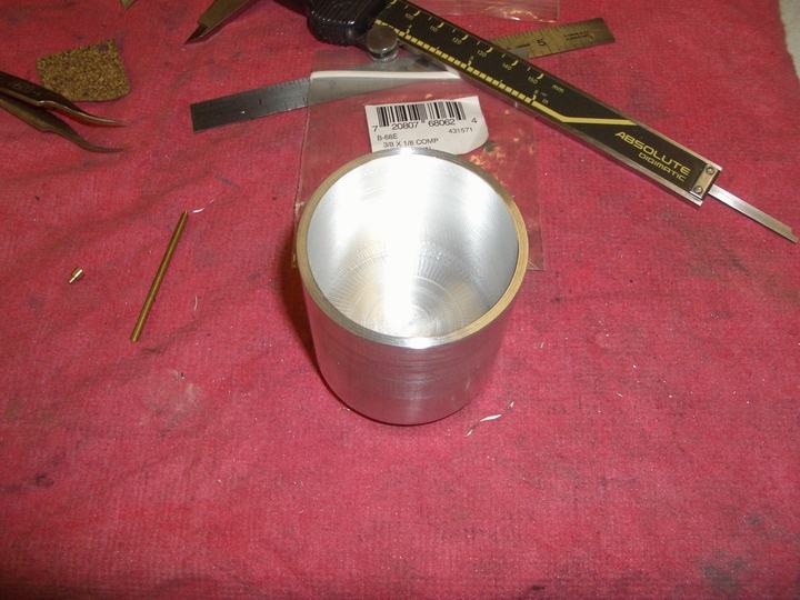 after boring i drilled and taped the bottom for a 10/32, but do not break threw!!! then i flip it around in the chuck and decoratively cut the bottom of the can. 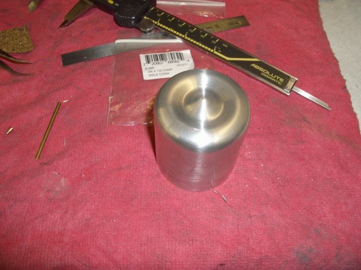 | ||
Aaomy |
then decorate the outside of the can how ever you want. i did 2 spiraling groves. you can easily buff it and call it good enough. for some reason i have a hard time calling anything good enough. 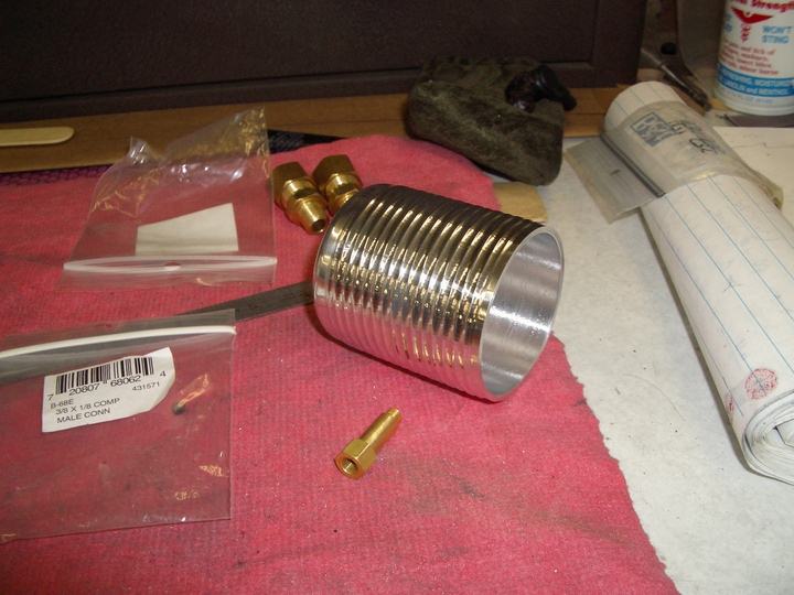 calling the can done and moving onto the mount now i use 2"x1/2" 6061. i drill and tap a 10-32 in the center to mount the can too. then i drill and tap the holes where the fitting will mount and where the air will exit. 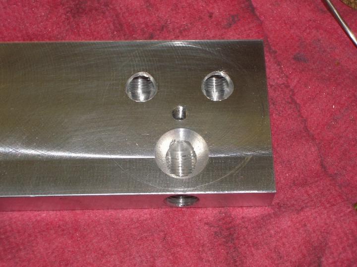 | ||
Aaomy |
 i then trimmed my material to length and started to shape my mount. the slot is for the 3/8" mounting bolt. 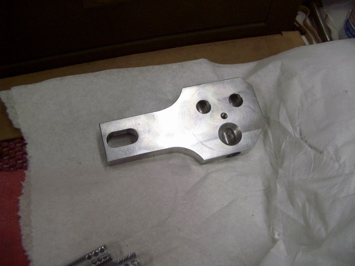 so here is my mount. you could shape this how ever you wanted to attach where ever you want. | ||
Aaomy |
next i started on the drop tubes. i didnt want the air just to enter and flow across the top of the can and out the exit. i started with some of the 3/8 al tubing. i wanted to make the air flow as far as possible and thew several " turns" to remove as much oil as possible before exiting and coating my leg and the bike. air will flow nicely around corners but the oil droplets will want to continue on and stick to the walls, form larger droplets and run to the bottom.. i took two 1.75 long pieces of the tubing and turned the ends down to press into the can mount .120 deep. this will hold them .120 off the bottom of the can and press them in as deep as they can go before obstructing the flow of the incoming air. i then drilled three rows of holes at the bottom to help insure proper air flow. here is how the tubes ended up looking. 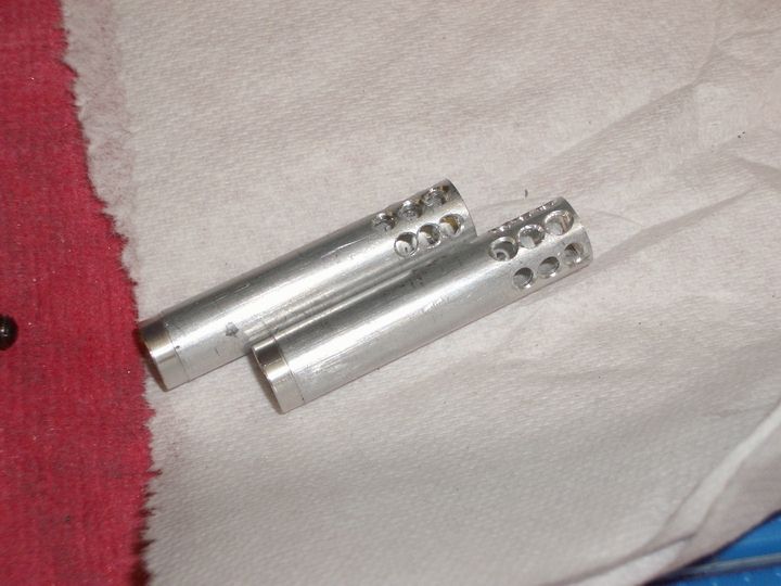 then they get pressed into the can mount facing away from the exiting top hole. 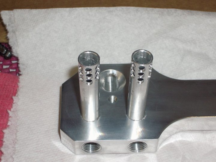 | ||
Aaomy |
now that the main parts are done its time to shine... i polished it some. not perfect, this bike gets ridden, but good enough. i quickly buff the two brass compression fittings and a al "air muffler" used to help quiet banks of air valves. for the center post i used a couple of brass 10-32 air line connectors. i am going to switch it out for either a 1/4 or 5/16 al center post taped both ends 10/32. i threaded a 10-32 set screw into the bottom until it bottomed out to give it a threaded post. this allows no externally visible mounts but the can just spins off. 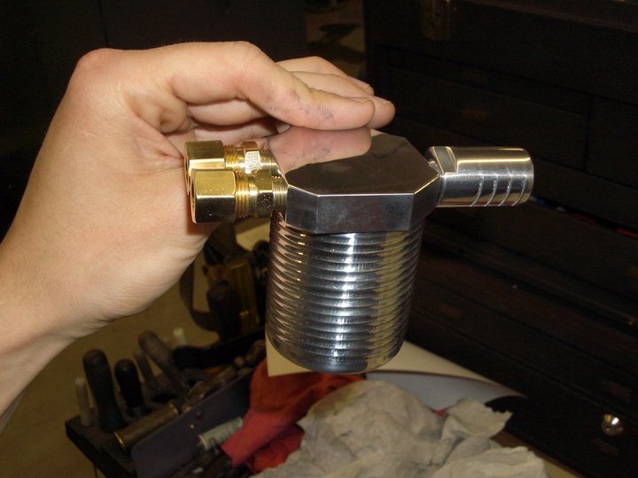 then its time to head home and slap it on the bike..in this picture you can see where it is going to be mounted to the rear head . this also gives the can a slight down ward slant to help oil flow down into it and also away from the drop tubes inside. 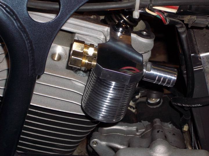 | ||
Phat_j |
dude, i gotta say, i'm very impressed...... u should sell the cans... | ||
Smokedaddy |
Very creative and nice work ... -SD: | ||
Aaomy |
thanks guy, your words of encouragement really help, bad day and i've wondered if people even want this stuff posted or not. koz you too, thanks for the informative pm. now that i know where i want the can i can return to the al tubing. 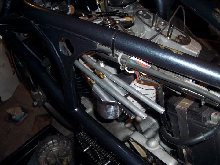 i bend it carefully around posts in my basement. you dont want to collapse it! i could have heated it to remove some of the temper, but i wanted it to keep its rigidity. after you get it in the shape you want then trim it to the desired length, and chamfer the ends. after a trial fit i quickly polish the tubing. 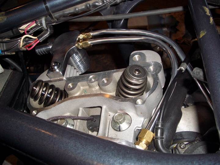 this picture works great for showing you how short and sort of direct this route is. sorry the tubing looks so bad in this picture, its picking up reflections and making it look all caved in. in reality its slightly flattened but the pictures make it look horrific. if you wanted you could place you catch can between the two cylinders on the left hand side of the bike and fill in the "horn area" . remember it gets a lot more crowded in their with the top motor mount on. | ||
Aaomy |
this image shows the close proximity of the rocker boxes when installed. also it shows how they hide the fittings. 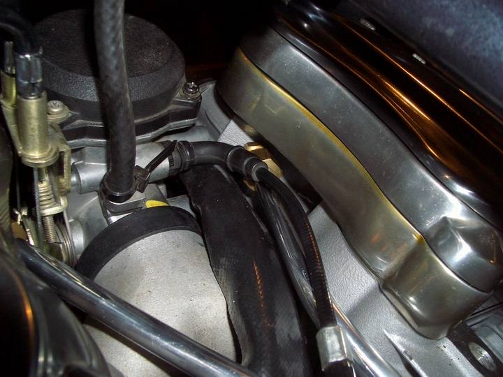 now with the top motor mount installed you can see just how crazy everything gets in there. but if you havent guessed it by now im not the kind of person whom walks away from a challenge. I RUN!!  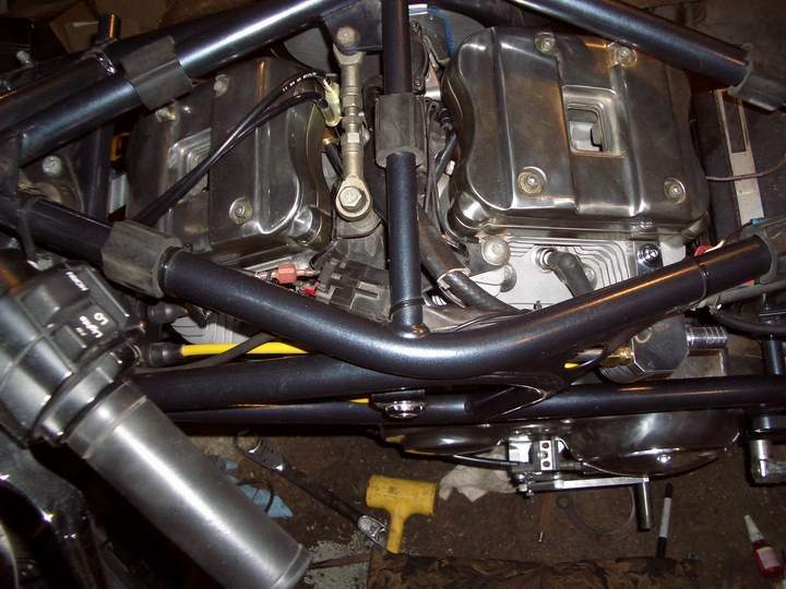 | ||
Koz5150 |
While you are in there making everything pretty, consider putting a chrome lid on the carb. It costs about $16 and actually is less noticeable then the ubly black plastic lid. | ||
Aaomy |
koz,, buy,,,buy,, and i thought by now you would have noticed.... i dont buy... i create.. guess that means time to get creative again hun... ps good call. guess ive been slacking, but wait till you see the air cleaner  | ||
Smokedaddy |
Just a point of information (in case you don't know). They make tubing benders with different radii. Plus, since you have a lathe, you can make a madrel yourself for 3/8" O.D. tube with a ballnose (depending on swing of course). The ones below have a 2 1/2" radii. Sounds stupid prolly ... but one of the classes I teach is precision bending (+- 1/16" overall, semi-conductor gas cabinets etc.) using electro-polished tubing. Of course the image below isn't in a clean room but the second one is. <duh> 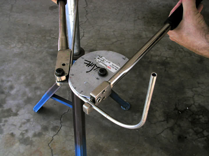 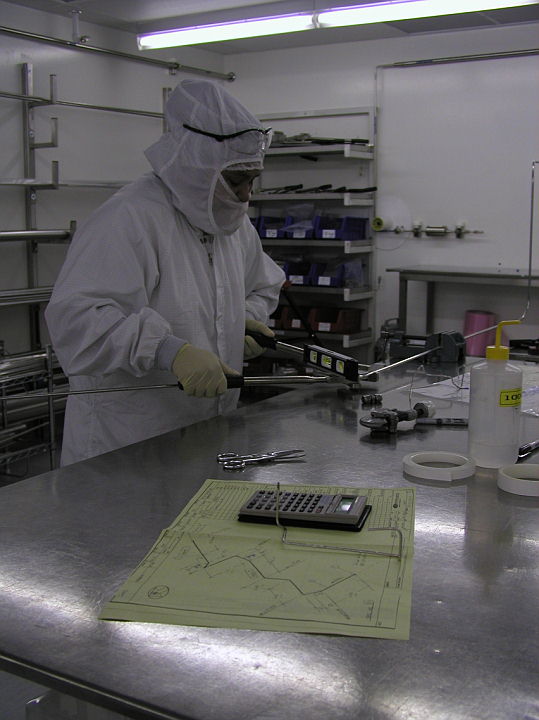 -SD: |