| Author | Message | ||
Pikeben08 |
Ok here we go. I used this website to figure most of this out: http://www.ecmspy.com/btwireless2.shtml My circuit is slightly more complex however for two reasons: 1. The first bluetooth module that I bought I thought would only support a 3.3V supply so I bought and adjustable regulator instead of the fixed 5v one that they use. 2. I also added some capacitors in the hope that it makes the supply voltage a little more robust. So you can use the exact setup that the EcmSpy website uses if you wish, I'm just posting what I used and I what I know worked. Parts Needed: Bluetooth Module � I picked one up from Virtuabotix on Amazon for $15. You can find cheaper ones that will probably work (~$10) but I figured the extra $5 was worth it in case I needed product support. FWIW The owner of Virtuabotix got back to me within minutes of me submitting a question, so I figured I would give them a plug. http://www.amazon.com/BT2S-Bluetooth-to-Serial-Slave/dp/B006RBK9ZW/ref=sr_1_2?ie=UTF8&qid=1397660767&sr=8-2&keywords=bt2s Deutsch Connector � Matches the stock Buell connector. Once again you could probably do this cheaper if you replace the connector on the bike, but I wanted to keep the stock connector since it�s a nice one. http://www.amazon.com/Deutsch-4-pin-Connector-housing-Terminals/dp/B00B4FCQCK/ref=sr_1_1?s=automotive&ie=UTF8&qid=1397661250&sr=1-1&keywords=deutsch+4+pin+connector LM317 � Voltage Regulator, I picked this up from RadioShack 220 Ohm Resistor � I picked this up from RadioShack 470 Ohm Resistor � I picked this up from RadioShack 1uF Capacitor � I picked this up from RadioShack 0.1uF Capacitor � I picked this up from RadioShack PerfBoard � To assemble the parts on, I picked this up from RadioShack Assorted wires for connecting components Shrink Wrap to encase everything once completed. Optional Supplies: Breadboard � I HIGHLY recommend grabbing one of these as well (once I again RadioShack). It will allow you to hook everything up and test the module before soldering so it�s a lot more forgiving if you make a mistake. FTDI or CP2102 � Not necessary since the BT module I listed comes with a 9600 baud rate, but you might need it if you have a race ecm (I didn�t even though I have a race ecm). You can also use this to change the name of your module to make it easier to find. http://www.amazon.com/CP2102-Module-Download-Serial-Converter/dp/B009T2ZR6W/ref=sr_1_1?s=electronics&ie=UTF8&qid=1397662106&sr=1-1&keywords=cp2102 ---------------------------------------------------------------------------------------------------- BT Module � Adjusting Settings You can skip to the assembly section if you are going to use the default settings on your BT Module. 1. Connect the BT module to the CP2102. Note: on some cheapo Chinese BT modules you will actually match Tx to Tx and Rx to Rx, but the virtuabotix one is as follows: a. Vcc to Vcc b. GND to GND c. Tx to Rx d. Rx to Tx 2. Download and install the driver for the CP2102 from silicon labs http://www.silabs.com/products/mcu/pages/usbtouartbridgevcpdrivers.aspx 3. Plug the CP2102 into your computer. You should see lights on the CP2102 and BT module. 4. Download CoolTerm http://freeware.the-meiers.org/ and Fire it up. You can also use Hyperterminal for this but I have a Mac and CoolTerm is pretty user friendly. 5. Go to the connection options area and check the following settings: a. Port set to the CP2102 (it might say SLAB USB UART something) you may have to click re-scan serial ports if it doesn�t pop up. b. Baud rate set to 9600 c. Data Bits 8 d. Parity none e. Stop Bits 1 6. Click Connect 7. In the Connections menu select Send String 8. In the dialog box that pops up type AT (in caps). 9. In the main screen you should see the BT module return the message OK. If you�ve gotten this far then you have successfully connected to the BT module. You can use the following commands to change any settings you wish. To change the PIN code send the device �AT+PIN####� <- replace #### with your four digit pin. The default pin is 1234, I didn�t see a need to change this. To change the Baud rate send the device �AT+BAUD#� <- replace # with the BAUD code from the look up table below (keep in mind you will have to change your CoolTerm/Hyperterminal Baud to that Baud rate if you want to continue to command the device). If you have a Race ECM you may need to change this to 19200. So you would send AT+BAUD5. CODE BAUD 1 >> 1200 2 >> 2400 3 >> 4800 4 >> 9600 (Default) 5 >> 19200 6 >> 38400 7 >> 57600 8 >> 115200 //MUST BE SELECTED MANUALLY (OVER SERIAL PORT) To change the device name send the device �AT+NAMExxxx� <- Where xxxx is the new name. I changed my name to ECMDROID so I sent AT+NAMEECMDROID When you are finished making changes click disconnect and unplug the usb from your computer. You don�t have to worry about saving changes as they are saved as soon as you send the command and don�t change when the module loses power. ------------------------------------------------------------------------------------------------- Assembly I used the following circuit design: 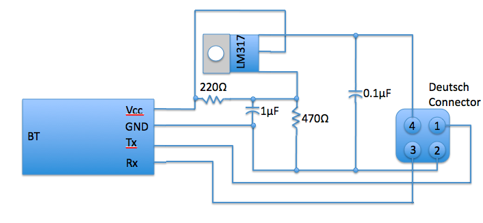 To make life easier you could replace the 317 with a 78L05 which is a fixed 5v regulator, then you wouldn�t need the resistors. As I stated before I thought my module needed 3.3V but most of the BT modules will work in a range of 3.3V-5V. My circuit will output about 3.9V. Here is my completed circuit on the breadboard: 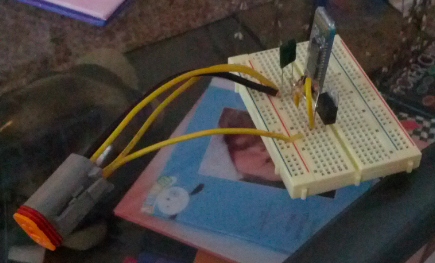 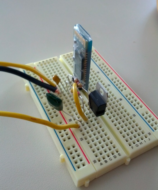 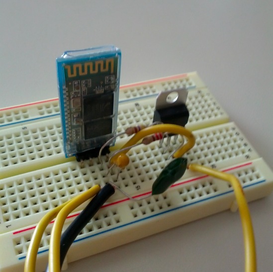 At this point you should be able to plug the module you built on the breadboard into the port on the bike. Once connected turn the key to On and the kill switch to run. You should see the light on the BT module start blinking. If it doesn�t you may have your resistors backwards (I made this mistake, with them backwards the circuit only outputs 1.84V which isn�t enough to power up the module). If the light is blinking then scan for the Bluetooth devices on your smartphone and pair the device with you phone. Once paired open the ECMDroid application and hit connect. You should see some messages fly by and then you should be connected and able to look at fault codes and all the other goodies. If you start the bike, you might lose connection if the voltage drops too low or if the breadboard is sitting on the bike (the vibrations might make some of the components lose connection, but this shouldn�t happen once you have the components all soldered together). Tada!!! I still need to solder all the stuff together on the perfboard and put some shrink wrap over. I�ll post an update once I get a chance to do that. | ||
Pikeben08 |
Oh one step I forgot. Although it should be obvious. When you hit connect in ECMDroid it will prompt you for a device. Select the bluetooth module you paired. This is when it is a little handy to change the name of the device to make it easier to find. | ||
Pikeben08 |
The walkthrough on the ECMSpy website is pretty good but the SparkFun module they used is expensive ($40) and pretty overkill for what is needed. | ||
Pikeben08 |
Ooops made an error in my circuit diagram. The. 1uF capacitor should go between vcc and gnd before the resistor. | ||
Reepicheep |
So what are you using at "the other end" of this? ECMDroid? Is that working, or are you using a PC? | ||
Reepicheep |
I see now that you mentioned that... You should switch from using that variable regulator to an LDO 5v regulator. That will keep it from dropping out so easily, and will be a simpler design anyway. So you will just have the regulator and a couple of capacitors, and I suspect it might be harmless to skip the capacitors anyway. I ordered the modem part, I'll try it with an LDO regulator (I have a pile laying around) and post how it goes. | ||
Pikeben08 |
I agree but I had already bought the parts so  | ||
Reepicheep |
Here is an updated schematic... I didn't put it in CAD yet, doubt i will, too easy to just build by hand. 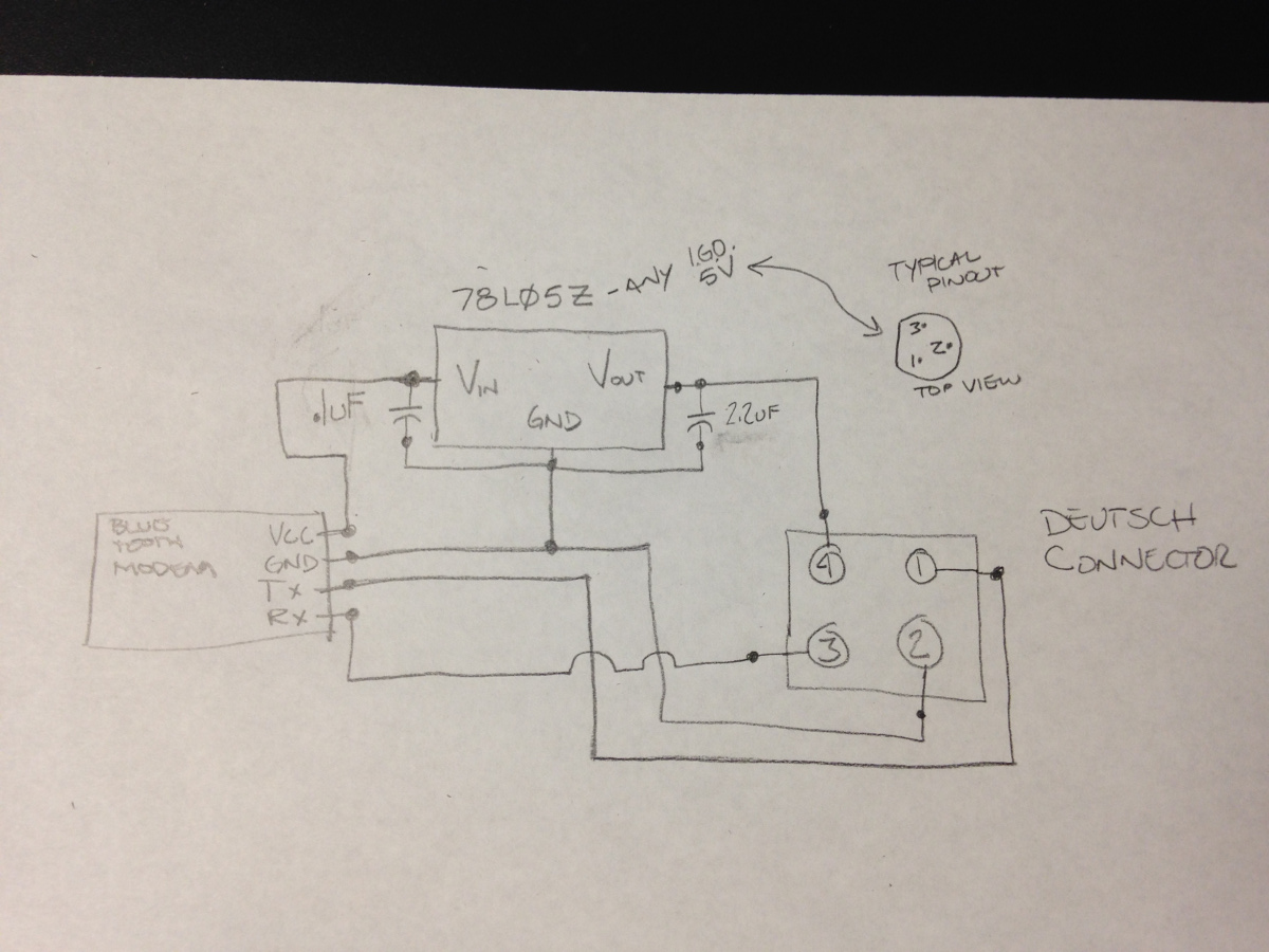 | ||
Reepicheep |
Oh, and pin 3 is VI, pin 2 is GND, pin 1 is VO (IGO means "Input, Ground, Output). And I bet it would work fine without the caps. | ||
Reepicheep |
(Oh, and note I haven't actually tried the above, I just replaced Ben's regulator with a fixed regulator like he suggested. LDO stands for "Low Drop Out". A normal regulator may need 7 volts or more to be able to step down to 5 volts without shutting down. An LDO regulator will keep working down to like 5.2 volts. | ||
Pikeben08 |
I agree it would work without the caps. I had just seen some posts about losing connection and thought it couldn't hurt. I just used PowerPoint to make my drawing because my handwriting looks like a two year olds. | ||
Pikeben08 |
So I got annoyed with using normal perfboard so I went to RadioShack and got the kind that has the copper circles to solder to. While I was there I picked up a 7805 5V regulator and went that route since it is simpler, though if you have already started with the 317 module, don�t worry it will work as well. I�ve updated the walkthrough to reflect that and am reposting it so all the info is in one place (I hate digging through various parts of threads to find the info I need). I used this website to figure most of this out: http://www.ecmspy.com/btwireless2.shtml My circuit is the same except I added come capacitors for a little extra robustness, but I�m sure it would work just fine without them. So you can use the exact setup that the EcmSpy website uses if you wish, I'm just posting what I used and I what I know worked. Parts Needed: Bluetooth Module � I picked one up from Virtuabotix on Amazon for $15. You can find cheaper ones that will probably work (~$10) but I figured the extra $5 was worth it in case I needed product support. FWIW The owner of Virtuabotix got back to me within minutes of me submitting a question, so I figured I would give them a plug. http://www.amazon.com/BT2S-Bluetooth-to-Serial-Slave/dp/B006RBK9ZW/ref=sr_1_2?ie=UTF8&qid=1397660767&sr=8-2&keywords=bt2s Deutsch Connector � Matches the stock Buell connector. Once again you could probably do this cheaper if you replace the connector on the bike, but I wanted to keep the stock connector since it�s a nice one. http://www.amazon.com/Deutsch-4-pin-Connector-housing-Terminals/dp/B00B4FCQCK/ref=sr_1_1?s=automotive&ie=UTF8&qid=1397661250&sr=1-1&keywords=deutsch+4+pin+connector 7805 � Voltage Regulator, I picked this up from RadioShack 1uF Capacitor � I picked this up from RadioShack 0.1uF Capacitor � I picked this up from RadioShack PerfBoard (the kind with the copper circles) � To assemble the parts on, I picked this up from RadioShack Assorted wires for connecting components A project box to put the completed circuit in. ECMspy just uses shrink wrap, but I thought this looked a little nicer. Optional Supplies: Breadboard � I HIGHLY recommend grabbing one of these as well (once I again RadioShack). It will allow you to hook everything up and test the module before soldering so it�s a lot more forgiving if you make a mistake. FTDI or CP2102 � Not necessary since the BT module I listed comes with a 9600 baud rate, but you might need it if you have a race ecm (I didn�t even though I have a race ecm). You can also use this to change the name of your module to make it easier to find. http://www.amazon.com/CP2102-Module-Download-Serial-Converter/dp/B009T2ZR6W/ref=sr_1_1?s=electronics&ie=UTF8&qid=1397662106&sr=1-1&keywords=cp2102 ---------------------------------------------------------------------------------------------------- BT Module � Adjusting Settings You can skip to the assembly section if you are going to use the default settings on your BT Module. 1. Connect the BT module to the CP2102. Note: on some cheapo Chinese BT modules you will actually match Tx to Tx and Rx to Rx, but the virtuabotix one is as follows: a. Vcc to Vcc b. GND to GND c. Tx to Rx d. Rx to Tx 2. Download and install the driver for the CP2102 from silicon labs http://www.silabs.com/products/mcu/pages/usbtouartbridgevcpdrivers.aspx 3. Plug the CP2102 into your computer. You should see lights on the CP2102 and BT module. 4. Download CoolTerm http://freeware.the-meiers.org/ and Fire it up. You can also use Hyperterminal for this but I have a Mac and CoolTerm is pretty user friendly. 5. Go to the connection options area and check the following settings: a. Port set to the CP2102 (it might say SLAB USB UART something) you may have to click re-scan serial ports if it doesn�t pop up. b. Baud rate set to 9600 c. Data Bits 8 d. Parity none e. Stop Bits 1 6. Click Connect 7. In the Connections menu select Send String 8. In the dialog box that pops up type AT (in caps). 9. In the main screen you should see the BT module return the message OK. If you�ve gotten this far then you have successfully connected to the BT module. You can use the following commands to change any settings you wish. To change the PIN code send the device �AT+PIN####� <- replace #### with your four digit pin. The default pin is 1234, I didn�t see a need to change this. To change the Baud rate send the device �AT+BAUD#� <- replace # with the BAUD code from the look up table below (keep in mind you will have to change your CoolTerm/Hyperterminal Baud to that Baud rate if you want to continue to command the device). If you have a Race ECM you may need to change this to 19200. So you would send AT+BAUD5. CODE BAUD 1 >> 1200 2 >> 2400 3 >> 4800 4 >> 9600 (Default) 5 >> 19200 6 >> 38400 7 >> 57600 8 >> 115200 //MUST BE SELECTED MANUALLY (OVER SERIAL PORT) To change the device name send the device �AT+NAMExxxx� <- Where xxxx is the new name. I changed my name to ECMDROID so I sent AT+NAMEECMDROID When you are finished making changes click disconnect and unplug the usb from your computer. You don�t have to worry about saving changes as they are saved as soon as you send the command and don�t change when the module loses power. ------------------------------------------------------------------------------------------------- Assembly I used the following circuit design: 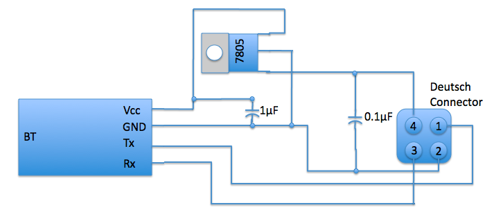 Here is my completed circuit on the perfboard (I didn�t do the breadboard this time since I already knew it worked) I would recommend doing this on the breadboard the first time if you have one: 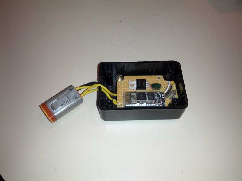 At this point you should be able to plug the module you built on the breadboard/perfboard into the port on the bike. Once connected turn the key to On and the kill switch to run. You should see the light on the BT module start blinking. If the light is blinking then scan for the Bluetooth devices on your smartphone and pair the device with you phone. Once paired open the ECMDroid application and hit connect. You should see some messages fly by and then you should be connected and able to look at fault codes and all the other goodies. If you start the bike, you might lose connection if the voltage drops too low or if the breadboard is sitting on the bike (the vibrations might make some of the components lose connection, but this shouldn�t happen once you have the components all soldered together). I had to trim the perfboard and drill some holes to get it to fit in the project box. Here is the assembled project box. 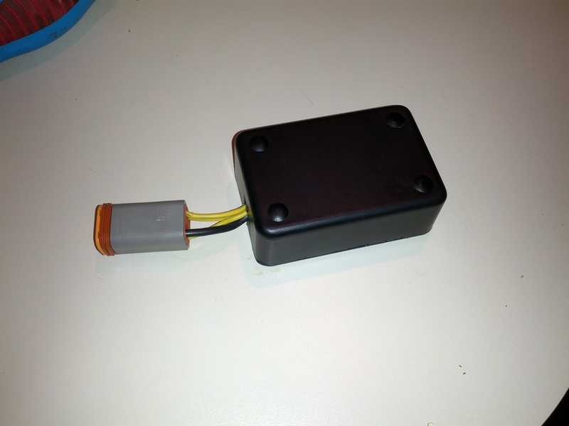 Tada!!! Enjoy! | ||
Reepicheep |
Thanks! Got the BT modem today with the intention of just reusing my old ecm spy connector, but it is short one pin. Worth keeping the old one intact anyway, so I just ordered the Deutsch connector from amazon. Now I have to wait for that to come in. I appreciate the detailed write up. | ||
Tq_freak |
Awesome! I think I have a new little project on my hands one question, what size project box did you use and where did you pick it up from? | ||
Pikeben08 |
3x2x1" project enclosure - radio shack I was hoping for something a little bit smaller but it was better than just shrink wrapping the board. Most of the stuff with the exception of the Bluetooth module and Deutsch connector came from radio shack. Not the cheapest or best selection, just the most convenient on my way home from work. | ||
Pikeben08 |
If you buy that box you'll need some #4 screws to hold the board down. Another minor annoyance was that there wasn't a board that fit the box so I had to trim mine. Not a biggy, just an extra step. | ||
Tq_freak |
Thanks Ben I'll most likely get something off amazon. there was a wider selection then locally and I need to get the Deutsch connector and Bluetooth there anyway. | ||
Tq_freak |
That little board doesn't have an output spot for the "connected" light by any chance does it? was thinking it might be nice to have an LED face mounted to the box so you can make sure it was working with out taking the box apart. I might be just over complicating things. | ||
Pikeben08 |
I actually had the same thought regarding the LED.  I seem to remember that there is an output pin along the side. I'll see if I can find where I saw that. It was for a different BT module but really they are all pretty similar. That being said, I have found that you don't need to connect to the module first (after you've paired it once anyway). Once you hit connect in ECMDroid it will make the BT connection automatically. It gives you status updates while it's connecting so you will know if you are connected or not. So there really isn't a reason to have an LED on the box. Other than it would look cool, which is why I may do it someday anyway. | ||
Pikeben08 |
here is the site I had seen with the descriptions of the side pins. http://mcuoneclipse.com/2013/06/19/using-the-hc-06 -bluetooth-module/ The virtuabotix module I had listed is an HC-06. So the pins should be the same. However, for better clarification or maybe even a how-to, I would just contact Virtuabotix. I'm sure they would at least let you know which pin to use. | ||
Tq_freak |
there website is being a Pita to ask a question. do you see any value to adding an on/off switch also? | ||
Reepicheep |
Along those same lines... wasn't the reason not to leave this connected / buried all the time that it was a battery drain? So what if it was powered off the ignition instead of off the ECM line? Could you then leave it perpetually connected? | ||
Pikeben08 |
Not sure on the battery drain. I know that module doesn't powerup unless the ignition is on and the kill switch is set to run. Personally I didn't think it was a big deal to take the seat off to plug it in. I didn't have any intention of leaving it plugged in anyway. But if you want to put a switch on the 12V line then more power to you. | ||
Tq_freak |
Yea after I asked about the switch I realized it was kinda over kill. More lights / buttons/ switches makes it better right? Ordered 90% of the parts last night! need to run to radio shack for the voltage reg and Caps. I'll post pictures of mine with its done. | ||
Tq_freak |
Got mine all together Monday. Works like a champ!! I am hesitant to post pictures cause I don't think the solder job is half as nice as yours. Thanks for the awesome write up. made the whole undertaking a piece of cake. | ||
Reepicheep |
I blew my first one up being sloppy when I accidentally flopped two of the wires assembling that Deutsch connector. Hopefully it didn't hurt the ECM, I don't think it did. New BT Modem on the way.  | ||
Pikeben08 |
"I don't think the solder job is half as nice as yours" You didn't see the back  Not my best work, but not my worst either. BT go boom! Oh no! | ||
Piratius |
So...if the Buell Diagnostic port at the connector outputs 5V on all of the pins (except ground, obviously). Is there any reason you couldn't just use one of these: https://www.sparkfun.com/products/12577 And just wire it straight up to a connector? I feel like that would be too easy, but it says it'll take any input from 3v to 5V. -Brad | ||
Cataract2 |
I used the BlueSmirf for mine, but while the TX is 5V the power line is 12V. Need to use a voltage regulator with an output of 5V or bad things happen. | ||
Pikeben08 |
You can use the bluesmirf if you want but its about $25 more than the one I listed. And as stated, applying 12v to it would turn out pretty poorly. |