| Author | Message | ||
Swordsman |
Hey guys, I got this relay from a guy at work, but I'm not 100% sure how I need to wire it up. The plan is to use this relay to power a set of fog lights. I want to use the Euro running light wire up in the headlight harness to trigger the relay, so any time the switch is on and that running light wire goes hot, the fog lights turn on. Here's the layout of the blades on the relay, and the diagram stamped on the side. Can someone give me a few pointers here? 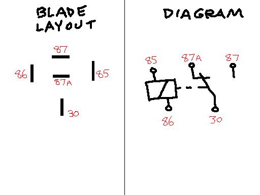 Thanks! ~SM | ||
Poppinsexz |
power through 85-86 to energize coil and close 30-87 allowing power to flow from 30-87 otherwise 30 is connected to 87a Clearer - hook your switch to 85 and hook 86 to ground. hook 30 to main power and 87 to the circuit you wish to power. (Message edited by poppinsexz on March 08, 2010) | ||
Fahren |
And you don't have to pull the euro-light wire out of its socket to use it - look into Posi-taps - you can tap into the wire (or the headlight power) without cutting anything, and if you decide to take off the mod later, the wire remains intact (except for the tiniest little pinhole where the tap point goes thru the insulation, but it's incredibly small). Posi-locks, posi-taps.... they are online. Webbikeworld did a good review of them. I love them for all wiring splices, taps, etc on a bike. | ||
Swordsman |
"hook your switch to 85 and hook 86 to ground" Is this for certain? It's exactly opposite of what the guy told me (one of the reasons I wanted to get a second opinion). Or is this one of those cases where it doesn't really matter? ~SM | ||
Mikef5000 |
It doesn't matter if power goes in 85 and out 86, or in 86 and out 85, it works either way. | ||
Swordsman |
So, with Poppin's explanation, does this mean that if I run a (+) line directly from the battery to 30 that 87a will be hot all the time, even when the bike is off? Just need to know so I can insulate it. ~SM (Message edited by Swordsman on March 08, 2010) | ||
Tiltcylinder |
85 and 86 are the terminals to power the 'coil' that pulls in the 'switch'(relay), it doesn't matter which is positive or negative (but one must be grounded and the other will get the positive from the 'euro light). 30 is the 'common' (hook to positive on the battery (use a fuse holder). Then with no 'power' to the 'coil' 87a will have 'power' and with power to the 'coil' (85/86 +/-) 87 will have 'power' (positive from 30 will flow to 87). | ||
Poppinsexz |
Swordsman- Yes also don't forget to put in a fuse for protection. | ||
Mtch |
found this, hope it helps. http://www.mp3car.com/vbulletin/faq-emporium/11789 5-faq-relays-how-they-work-how-wire-up.html sounds like use 30 from your battery, 87 to the fog lights, 85 from the running light, 86 to ground. use 87a only if you want something powered when ignition is off | ||
Swordsman |
Cool! Thanks for the info! I already have a fuse holder + fuse... came with the lights. ~SM (Message edited by Swordsman on March 08, 2010) | ||
Ratyson |
Is there a diode in the relay (probably not) between 85 and 86? If there is, it will matter which one you hook to ground, and which one to the power source. You can check this by using a meter with a diode tester. If you just have an ohm-meter, measure like this: Red -> 85 Black -> 86 Then reverse. If both show zero ohms, no diode. If one measures open or a very large number, that is the diode. If not, you may want to install one. They are used to restrict reverse voltage during switching. Diodes only allow current to flow in one direction. (Message edited by ratyson on March 08, 2010) | ||
Azxb9r |
Which is pos and which is neg on the relay windings only matters if it has a diode. The schematic you have does not show a diode, but it is possible that whoever drew the schematic left it out. Look on the side of the relay, it will show a diode linked across the windings if it has one. The main purpose for the diode is to absorb voltage spikes. This is only an issue with ECM controlled relays, you should not need one for a switch operated light relay. If it does have a diode, and you hook it up backwards, you will blow the diode but the relay will usually continue to work since the diode is in parallel with the winding. | ||
Azxb9r |
Btw... 85 is usually the pos terminal if it does have a diode. (Message edited by azxb9r on March 08, 2010) | ||
Swordsman |
That schematic is stamped into the side of the relay case, so I doubt anything was left out.  ~SM | ||
Azxb9r |
In that case... no diode...no worries  | ||
Fast1075 |
The diagram on the relay shows the switch set in the de-energized condition. Terminal 30 is the common power leg..de-energized, power goes thru terminal 87a...when energized the contact switches and power goes from terminal 30 to terminal 87. This relay is known as a "single pole, double throw" relay...terminals 85 and 86 are the coil terminals...one (either) goes to ground and the other goes to the switched power source (horn button for example) to activate the relay | ||
Swordsman |
Yeah, I really don't need the 87a part, but I got the piece for free, so I'll just insulate the 87a blade and call it a day. ~SM | ||
Hootowl |
The diode is there to provide a discharge path for the coil. Not providing a path creates a very high voltage, depending on how much energy is being stored by the field (current potential) and the resistance the current has to be pushed through. E=IxR. Air gap = very large R, so a small amount of current can produce a very high voltage as the power is removed from the relay. This sounds horrible, but in practice, the tiny bit of stored current simply arcs across the contacts of the switch as you're opening it, so not having a diode is not a big deal. |