| Author | Message | ||
Benm2 |
So I spent some time this winter rebuilding, revalving, and respringing my rear Showa recall shock.(14.5" lg.) The shock CAN be rebuilt by someone with patience, spare time, and a good selection of tools. The only tool I had to borrow was a hydraulic press, although in a related search of BadWeb I did a while ago, someone has made their own press from allthread and some custom ends. I found a fair amount of useful knowledge from searching the web regarding the rebuilding of standard Showa shocks, and it was helpful in getting the shock apart. In addition to that, I got a valving kit from RaceTech & the included video was also helpful with some of the more-fun parts. I also managed to find someone to make me a custom spring, with a rate that I got (again) from searching both BadWeb and the net. There are also posted resources on the BadWeb for rebuilding the stock shock, I'll try to gather them up as well. Just as a reference, for comparitive costing: 1. RaceTech 40mm Shock piston kit - $169 2. Seal head rebuild kit - $40 3. Custom-rate rear spring - $130 4. 1 quart shock oil - $20 So I totaled out around $360, including new valving & a new spring. Not too bad, and still a fraction of the cost of even the low-end Works shocks. Overall, it took me about 10 hours to disassemble, clean, revalve, and rebuild the shock. Depending on your skill with little screwdrivers & dental picks, you might be able to get it done faster. | ||
Benm2 |
Once the shock is off the bike, take the time to clean it off. Mine was filthy, with a combination of road grease, chain lube, oil, & dirt. The next trick is removing the nitrogen pressure from the shock reservoir. The reservoir as-delivered has no visible valve, but there is a shraeder valve under a pressed-in aluminum cap at the end of the reservoir. The cap pretty much gets destoyed when you remove it. RaceTech says drill a small hole in it, being careful only to go thru the aluminum cap, then prying it out with a small screwdriver. The cap is about 1/16" thick material. Under the cap is a small valve, like a tire fill valve, with a cap. Remove the valve, and release the nitrogen pressure just like you'd let the air out of a tire. You should get a little "pfft!" and that's that. Here's some pictures of the reservoir in various states of disassembly: 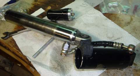 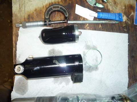 I personlly found it easier to work on removing the spring & disassembling the main body after I drained the oil & removed the remote reservoir and hose. The EASIEST way to start getting the oil out of the shock is to remove the hose between the reservoir and the shock body. Again, AFTER you release the nitrogen, you can just remove the hose & its copper washers. BE CAREFUL TO NOTE OR TAKE PICTURES OF THE OREINTATION OF THE HOSE ON BOTH THE RESERVOIR & THE BODY. If you put those back in the wrong place, you won't be happy. Also note: OIL WILL LEAK OUT EVERYWHERE. Perform the hose removal with the shock in a bucket or tub. Removing from the shock body is easiest, but note: the chromed "nut" that is closest to the shock body is NOT removable, only the banjo bolt comes out. The connection at the reservoir is trickier to remove, since its connection to the reservoir isn't rigid. The hose-connection end of the reservoir is another chunk of aluminum held into the reservoir with a snap ring. I held onto the flats of the cap in order to remove the banjo bolt at that end. At this point I started putting all the collected parts in ziplock bags, with little paper labels & hand-sketches. I clean the part with solvent, put it in the baggie, then bag the notes, and put them in the baggie too. (oil WILL get on your paper notes & make some critical note or diagram illegible). Here is where you can start to love the little retaining rings that hold the entire recall shock together. While GENTLY clamping the reservoir, push the valve & its cap into the reservoir. It will likely be "hung up" from sitting in the same place for a long time, but it should start to move down. If you get it to move a little and it stops, try releasing a bit more air from the reservoir by depressing the valve. Once you get it down about 1/8", you can see the little retaining ring that holds it in (to the right of the reservoir in the second picture above). Patience, some small picks & screwdrivers, and persistence help trying to get them out. This one's good practice, the ones on the shock seal head are the final exam. Once you get the ring out, GENTLY pull up on the cap & pull out the bladder. Clean, label, store. At the other end of the reservoir is the opposite cap (the rebound adjuster housing)held in by another snap ring. Using the same sequence of cussing, use some picks or small screwdrivers to get that one out too. Then pull out the cap. This particular cap on mine was filthy, I could hear the grittiness when I was turning it to pull it out. For this cap I cleaned it, cleaned the reservoir housing, cleaned the ring, then put them back together & stored them as an assembly. | ||
Gowindward |
Ben, This is greatly appreciated! Leave it to an engineer to take the mystery out of these things. LOL Any indications of cause of failure of the seals such as dirt and raod grime getting to the seals, or just old age? I'm looking forward to more info. Thanks, Loren (Message edited by gowindward on April 15, 2009) | ||
Oldog |
More please sir, rebuild is expensive to have done race tech CA 180 ~ 200 After shocks 336 | ||
Benm2 |
Alright, onto the fun parts. A few quick notes: if you have the hose off now, the shock will make a mess. You can't get all the oil out, it will leak all over the place for a while. Get out what you can, then wrap the end in a rag to absorb drips & such till you get it the rest of the way apart. At the ROD END of the shock (the aluminum end) are the adjuster & locknut for preload. The locknut can be removed, and threaded over the end of the shock. Do the label/store thing again after you clean it up. Next, wind ALL of the preload OUT of the shock. This is done by "tightening" the sleeve nut, ie moving it away from the eye.  The picture above has all the preload out, among other things. The picture above leads to the next step, which will be removing the can and spring. You'll need a press to compress the spring to get it apart. * Notes - the spring on the shock carries a fair amount of force on it even with no load on the shock. From my calculations, the spring (M2) carries about 350lbs at minimum load. You're not getting it apart without a press, and BE CAREFUL!* In the picture above, you can see that the upper preload nut is no longer attached to the can, which is sitting below it. In order to get to that point, you need to press down on the nut (into the can) while supporting the other end of the can. You'll need to push it down about 1/4" or so to get to the NEXT snapring. Get about the business of digging that one out. When you release the press (Slooowly), the can will move down to the point where it is firmly pressing against the remote reservoir attachement fitting. Don't leave it this way for long. Once you get the snap ring out (more of a round wire ring, don't think it has little eyes on it), you can thread the nut off the end of the shock. Set those aside for now, and get back to the press. The next trick here is to push down the shock body spring perch, which is just visible at the top of the can in the picture above. Support the can again, and push down on the top of the spring perch. Again, go down about 1/4" and dig out another round wire snap ring. Release the press SLOWLY and you can now take the spring perch off the shock body. The spring should be sticking about 1/2" out of the can after you have this done. Store the perch & wire together. You can now lift the spring out of the can. No matter how well you cleaned the outside of the shock before you started, it will be filthy and govered with black dirt/oil/grease combo material. Clean at your leisure. Likewise, you can lift the can off the shock now too. ** NOTE there are THREE little plastic bits inside the shock can, and they have a specific order that the go in. When you lift the can off and turn it over, pull them out carefully to make sure you know the order they go back in. (sorry don't remember myself right now) ** The plastic bits inside the can will also be filthy, as with the inside of the can. Clean/store. NOTE: the body of my shock showed some visible wear where the "seal" at the end of the can rode on the shock body. It was enough to get through plating, but that seems to be about it. I don't expect that these things will be able to be rebuilt multiple times before that wear becomes an issue!! | ||
Benm2 |
After all that, you should just have the shock body assembly in your hands. The next part of the disassmbly can be done two ways, depending on your dexterity. I'll cover the one with LESS disassembly first. At the ROD end of the shock body (where the rod comes out) the parts are in this order: 1. Shock eye 2. Shock eye locknut 3. Rod 4. Shock rubber bumper 5. Shock bumper end cap 6. Shock seal head 7. shock valving The picture below shows all those items, in order (the rubber bumper is hidden by the end cap): 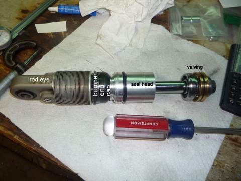 The bumper end cap is pressed into the shock body. I coaxed mine out with a sharpened centerpunch and a small hammer, working my way around the diameter. Don't hit anything hard here, it might make you feel better but might ruin the shock. Again, patience. Now the toughest part of getting it apart. The seal head is held in by THREE snap rings. With what's been done so far, you can't remove the end cap. All you can do is wire/tape it up against the end of the shock eye. Extend the shock eye, and look down inside the shock body. The first snap ring to remove is around the OD at the top of the seal head. After you get that one out, turn the shock over. The next one should fall out in your hands (its a backup) The next one is the most difficult of all of the snap rings to remove. In order to access it, you'll need to push the seal head into the shock body about 1/4". Again, mine was hung and took a bit of force to get moving. Don't go too far, as it reduces your available work space since the rod moves in with it. Then fish that one out. Make a sketch, noting the assembly order. Clean up the rings, label, store. Now the whole assembly (as shown above) can be pulled out the end of the shock body. Be careful & take your time, and remove any burrs you may have made getting the rings out. Be careful so as not to tear the oring on the seal head. ** Disassembly note - I didn't disassemble it this way. I just kept taking thing apart that were in my way, so I took apart more than I really NEEDED to. That being said, removing the shock eye & locknut from the rod allows for MUCH better access to the seal head rings during disassembly ** Also, your stock setup won't look exactly like the picture. The Showa piston is black, this picture is mine during re-assembly with the gold valve on it. | ||
Oldog |
More Pix? | ||
Bhillberg |
from the parts list in the original post it is more expensive to do yourself than have it rebuilt? I am all for working on stuff myself but if it's cheaper to have someone else do it then why bother? I mean if you really just enjoy it or are just plain curious more power to you. I'm just posing the question and seeing if it is actually more expensive this way | ||
Benm2 |
A rebuild & a revalve are two different things: a rebuild will be new oil, some new orings, and a new shaft seal. A revalve will cost more for parts and additional labor, then add to that again for a new spring. Depends what you want. | ||
Benm2 |
A better picture of the seal head arrangment inside the shock. 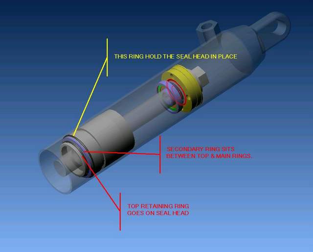 | ||
Gowindward |
A source for rebuild parts. http://www.moto-pro.com/ | ||
Benm2 |
Moto-Pro was my source for the rebuild parts AND for the custom spring. In addition to that, John (the owner) spent at least an hour on the phone with me during my rebuild helping me out with question. GREAT guy with excellent service. He's located in Washington (the state), so keep that in mind when calling. | ||
Gowindward |
Ben, Do you have any part numbers or links to the items you purchased from Moto-Pro? Looks like there is a 14mm and a 16mm Showa rebuild kit. Which is it? Do you know how much nitrogen pressure was put on the reservoir? | ||
Benm2 |
Going from memory, the 16mm kit is the right one, but the bushing is wrong. You'll need 2 bushings, if I remember right they are each 15mm lg, and the Buell shock uses two. The standard rebuild kit only comes with one bushing. The top dust seal on the seal head is a bear to get out. The bottom one is under a washer held in place by another snap ring. | ||
Brinnutz |
This is interesting...I'm watching. =) | ||
Oldog |
Ben could a spring compressor tool be made from some suitably sized all thread rod and some steel shapes or thick bar? Perhaps some pipe coupling collars to push in the right places? How much oil and what was the gas pressure in the bladder? (Message edited by oldog on April 16, 2009) | ||
Benm2 |
Jim, If you do a search of the "old school" section, you can find some pictures of a spring compressor that someone made for the shock from all thread & some plates. It certainly could be done easily enough if you don't have access to a press. I used less than 1 quart of oil. I used BelRay HV1 10W, which was somewhat thicker than what RaceTech recommended. They told me that after I had the shock assembled with oil in it, so I left it. They said to use their Race Tech US2 oil, which is very expensive (somewhere around $30/qt plus shipping). Even so, the BelRay cost me $20 plus shipping. I recharged the bladder to 185psi. There is a local bicycle shop by me that has the nitrogen for rebuilding/revalving bicycle shocks. | ||
Oldog |
Are you going to post any notes on re assembley? | ||
Benm2 |
I'm not done with disassembly yet! The bigger posts take me about 45 minutes to put together with the pics & diagrams. It just takes a while. | ||
Oldog |
The 3 D is Killer You have got me motovated to try it Boss told me I can get some steel outa the shop for the press plates | ||
Benm2 |
Go to Roadracingworld's website, and look at the new Mladin clip. During the clip, they show a mechanic starting to disassemble a shock with a bottle jack and a tower that holds the eye. Thought that was slick, to see how Yosh changes springs at the track. | ||
Benm2 |
On now to another challenging step. First, I'll tell you the "right" way to do it, then what I did. At the end of the piston rod assembly, there is a 12mm nut. This nut is peened at the end on opposite sides, a more permanent version of loctite:  According to various sources like RaceTech, the peening can be oh-so-carefully ground away on the nut with something like a dremel tool. If you do this, be VERY careful not to damage the threads on the shaft shock. Also, there IS valving INSIDE the shock shaft itself that is held in place by more peening at the end of the shock shaft. The nut can be replaced easily enough. You can order it with your rebuild kit, and new ones come with Gold Valve kits. Don't worry about ruining it! If you don't have the assembly clamped vertically into a vice, now would be a good time to do that. Make sure the nut is up. Once the peening is filed away, remove the nut BUT NOTHING ELSE!!!!! The next part is important: TAKE A PICTURE, DRAW A DIAGRAM, ETC. Do whatever it takes for you to remember the orientation of the valving piston & shim stacks. The rebound & compression stacks are NOT the same, and you DON'T want to put this back on upside down. Now, get a small screwdriver or a length of wire. Stick it the end of the shock shaft, holding onto the handle end with one hand, keeping it vertical. Now grab the valving assembly (including the funny looking shiny silver thing) and pull them off onto the screwdriver. Now, what I did. I just took off the nut and boogered up the nut & shock rod threads. I happen to own a fine-thread M12 die, so I wasn't worried about chasing the threads. (Message edited by benm2 on April 17, 2009) | ||
Benm2 |
Here's a separate picture of my valving assembly (piston & shims) on a piece of safety wire:  | ||
Benm2 |
Here's a neat little item, though I'm not quite sure why the shock needs it:  This little thingy is a one-way valve assembly that controls the flow of oil through the center of the piston shaft. It has a floating washer in it (held in by a snap ring) that will allow oil flow in one direction, but not the other. 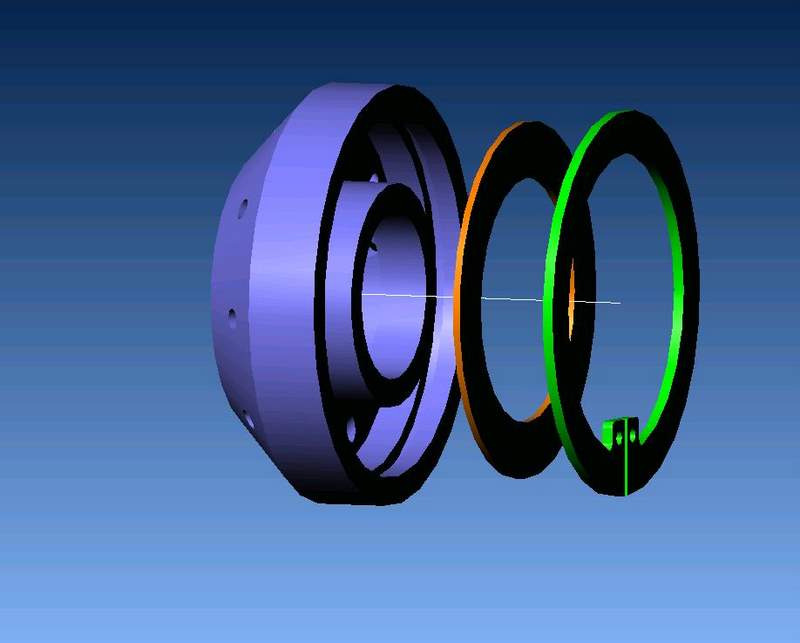  This little part is combined with a check valve assembly INSIDE the shock shaft that only allows one-way flow through the center of the shock shaft. Why is that important? Well... During suspension compression on your Buell (pull shock only!), you are actually EXTENDING the shock. When that is going on, oil needs to flow from one side of the piston to the other side. The valving shim stacks are mostly made to handle high-speed valving, whereas low speed damping is handled by the orifice in the middle of the shock shaft. High speed compression damping keeps the shock from "locking up" on big hits & becoming harsh. Low speed helps with wallow, among other things. On the rod eye end of the shock is the compression adjuster. Via a tapered-ramp setup & a tapered needle, this allows for adjustment of the orifice size that the shock oil flows through to get from the top side of the piston to the bottom. Simple, right? Here's the tricky part, and one of the reasons why I don't think the recall Showa is the POS that everyone says it is: one a lot of shocks, this orifice is open in both directions. So on a "regular" shock during rebound, when the oil is flowing back to the top side of the shock, it can go through the same hole. So if you change your low speed compression setting, it will also affect your low speed rebound settings. On the Buell Showa recall shock, this fancy check valve setup prevents oil flow through the low speed compression orifice during rebound. (say that 10 times fast). If you look at RaceTech's website, you will find that this "special feature" can be purchased from them by buying a shock nut with a built-in check valve. Your crappy recall Buell shock doesn't need it!!! Why do I question its use? Because there is a one-way check valve inside the shock shaft. I verified that with a rubber-tipped air gun. But since I don't design motorcycle shocks for a living, I'm willing to give Showa's engineers the benefit of the doubt. | ||
Benm2 |
Now if you're only doing a "standard" rebuild, the next thing you'll need to remove will be the seal head. Just pull it off, simple enough. On the piston-side of the seal head, you'll find another snap ring. Take it out, then you can get out the main shaft hydraulic oil seal. It is two pieces, and there is a backup washer. Now is an important time again to stress: MAKE NOTES, PICTURES, ETC. You don't want to put your new seal in upside down. On the opposite side of the seal head is the dust seal. This seal contacts the OD of the shock rod, and is mounted to the seal head via its ID. Strange? It will make sense when you see it. Here's an important note: I COMPLETELY DESTROYED MINE TAKING IT OUT. The seal's mounting surface had bonded itself to the aluminum seal head, and took a fair amount of brute force to remove. Once I got it out, I removed all my screwdriver scratches (uh, I mean burrs..) with a small file & emery cloth, and installed the new seal. Be careful when installing the new seal NOT to push on the CENTER ID portion of the seal, you'll break it. If you have a new hydraulic seal, its installation should be self explanatory once you take the old one out. | ||
Benm2 |
Here's a 3-d shaded image that shows how the compression adjuster rod changes the low speed compression orifice size (note that I hid the piston & shims in this view, so you could see the tapered needle & seat): 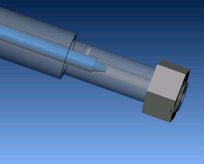 Here's how it works at the rod-eye end (where you adjust it) 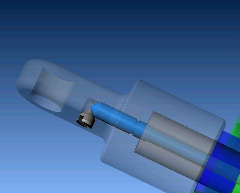 | ||
Someday |
Benm2, Great article! | ||
Oldog |
I'm starting on the press for the spring tonight, I may try to remove the spring too, the shock has a pressed in bumper? that you had to "dig out" with a punch and hammer? | ||
Benm2 |
Here's a better picture of the bumper cap, its the green part. You have to get it at the seam between it and the shock body, and work your way around it, pushing it up towards the rod eye.  | ||
Oldog |
Thanks for the heads up! I have got the shock and the spring apart, the shock is still charged and sealed. Word here, when removing the spring keeper on the shock its self, compress the spring and rap on the body eye to free the keeper if it does not move down, then you can get the wire ring out. the tool is made when I am done any one who wishes to borrow the tool may do so for the return freight. |