| Author | Message | ||
Hemicbx |
I’m preparing to build up a Palm cable for ECMSpy. I’ve read a lot and determined the pinout on the palm end but I have a few questions about the actual interfacing of the diagram on the ECMSpy page with the ECM and the Palm. Palm m500 (universal connector) pins are: 1&7 are ground (they’re connected internally) 10 PDA Receive 11 PDA Transmit 16 PDA charge (requires 5v) I’ve added the ECM and the Palm to the diagram from the ECM spy page: 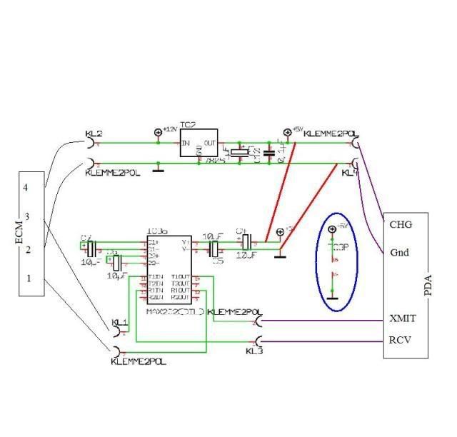 If the pic below is too small to see all the detail, the link is here. http://www.ecmspy.com/kabel_pda.shtml From the notes on Badweb & the ECMSpy pages I have some questions just for verification: 1. Is there really useable +12Vdc available on pin 4 of the diagnostic connector? 2. The signal translation circuit (lower half of drawing) needs +5v power. I show this coming from the voltage regulator circuit (top half of drawing) in red. Is this correct? 3. Can I tie the output of the voltage regulator circuit to the palm for charging as shown in purple? I worry a little bit about tying the comms & charge to the same power supply. 4. Would it be better to build two voltage regulator circuits, power them both from the same +12v point and use one to power the comms & one to power the charging? 5. I don’t really understand what the little portion in the blue circle is for or what it’s really connected to. Thoughts? I think my intent here is to use a little hobby enclosure with the circuitry inside. One end will have a pigtail to the ECN diagnostic connector. On te other side I will put a male DB9 serial connector so that I can just use a standard serial Palm cable and plug it in. Any thoughts, words of wisdom, or voices of experience would be a huge help. Thanks, Hemicbx York, PA | ||
Aptbldr |
Is this a proven Palm cable option: <http://www.xoptiinside.com/cables>? I can grasp its instructions. Schematic, in Hemi's post above, is over my head. | ||
Id073897 |
1. Is there really useable +12Vdc available on pin 4 of the diagnostic connector? Yes. 2. The signal translation circuit (lower half of drawing) needs +5v power. I show this coming from the voltage regulator circuit (top half of drawing) in red. Is this correct? Yes. 3. Can I tie the output of the voltage regulator circuit to the palm for charging as shown in purple? Yes. I worry a little bit about tying the comms & charge to the same power supply. Why? 4. Would it be better to build two voltage regulator circuits, power them both from the same +12v point and use one to power the comms & one to power the charging? No. 7805 is up to 1 Amp. 5. I don’t really understand what the little portion in the blue circle is for or what it’s really connected to. IC3 power supply on pin 15 and 16. On te other side I will put a male DB9 serial connector so that I can just use a standard serial Palm cable and plug it in. Definitely NOT recommended. Alternative setup: http://www.botkin.org/dale/rs232_interface.htm http://www.buelletinboard.com/forums/showthread.ph p?t=3141&highlight=cable&page=18 | ||
Hemicbx |
Aptbldr, I don't know how I missed that. I kindof consider myself a regular at Xopti's site. Thanks. ID073897, Thanks for all the feedback. I like the alternate setup you gave me in the link to botkin.org. Have you used that method? Hemicbx York, PA | ||
Hemicbx |
ID073897, one more question. The section in the blue circle shows 5 & gnd on pins 15, & 16. However, the chip view itself shows power on 2 & 6. Does it need power in both places? | ||
Id073897 |
Thanks for all the feedback. I like the alternate setup you gave me in the link to botkin.org. Have you used that method? No. Although it is said to work properly, a simulation showed slightly too low signalling voltages. However, the chip view itself shows power on 2 & 6. A MAX232 has Vcc on pin 16 and GND on pin 15. http://www.datasheetcatalog.org/datasheet/texasins truments/max232.pdf |