| Author |
Message |
    
H2owerker
| | Posted on Wednesday, October 01, 2008 - 08:56 pm: | 


|
OK. My power supply was the problem.
After getting past that, I have (with the help of an electrical engineer) built a slightly different timer. All the components I used were spec'd the same as Reep's design.

Please excuse my MSPaint skillz.
R1, and R2 are 10K 1/8th watt resistors
D1 is any silicone switching diode
C1 is a 2200 uf
C2 is a 220 uf
P1 is a 0-100k potentiometer
T1 is a Darlington transistor (from Radio Shack)
SW1 is the Passing flasher switch located on the left hand controls. This should not be diverted to the circuit. It should only be tapped into as an alternate source to charge the capacitors instantaneously.
CR1 is the relay coil
I tied the "Passing" switch into the circuit to defeat the delay and turn the lights on when wanted. I may try adjusting the potentiometer to not allow the timer to "time-out" while running solely on battery power, but work after the generator brings the voltage up to 13.8v or the passing flasher is pressed.
(Message edited by h2owerker on October 01, 2008) |
Reepicheep
| | Posted on Thursday, October 02, 2008 - 08:25 am: |
|
Nice touch with the instant charge approach!
Don't dial P1 down too far when setting up, or you will blow your transistor. And likewise, make sure you always have the relay in the circuit, if you bypass that for some reason that'll blow the transistor as well. But those two things ought to be easy enough to avoid.
Why C2? Unless there is a diode missing from that schematic, I don't think it does much.
Y'all need to stop baiting me. Time to redesign the circuit with a LM339.  |
Court
| | Posted on Thursday, October 02, 2008 - 08:36 am: |
|
You guys have got to hurry. I feel like your day jobs may be impeding the process and, to that end and in view of the pace at which I am adding electrical load to my Coolysses, I may need to contact your supervisors and request a sabbatical to allow you more time to devote to this project.
HURRY UP !
P.S. - Don't even thing about cutting corners . . . . the final product is going to have to get past the scrutiny of a Danish Surgeon! |
Reepicheep
| | Posted on Thursday, October 02, 2008 - 11:57 am: |
|
I potted the prototype meter last night. I'm trying to figure how to make it really hold up. I think I'll build you a fresh one, and completely seal it, and just bring the LED's out. I'll have to dig up Ft Bastards pictures of the dash panel, I looked from the outside and it appears I can wedge 4 LEDs in a circle pattern in there.
If you see one red light, you are down to under 50% battery capacity and not charging. You see one green light, you have a reasonable charge level for a bike not running but ignition on. If you see two green lights, you have a reasonable charge level for a running bike that is charging the battery. You see two greens and another red, your bike is currently overcharging your battery.
The delay will be easier... using the LM339, I think I can build a really flexible device with just a few simple parts.
How long do you want between the time you switch on the ignition until you have the engine already running, before the HID kicks on? Mine is currently 90 seconds, which is a bit on the long side. I am sometimes half way down my street before the lightning strike hits. I'm thinking 60 would be better. |
Court
| | Posted on Thursday, October 02, 2008 - 12:11 pm: |
|
60 would allow time for a full recovery from a cold start, would it not?
Is it FtB who had the photos of the install in the vacant dash spot? If so, I'll get the link to Henrik so he can refer to it when he does the install.
Very cool stuff. |
Reepicheep
| | Posted on Thursday, October 02, 2008 - 04:50 pm: |
|
Here it is...
http://www.badweatherbikers.com/cgibin/discus/show .cgi?tpc=142838&post=1067990#POST1067990
Should I just send Henrik a pile of parts and a schematic?  |
H2owerker
| | Posted on Thursday, October 02, 2008 - 09:32 pm: |
|
I connected the timer to the bike today, and set P1 so the capacitors will not charge sufficiently (no matter how long the bike sits) to switch the transistor. Once the engine is started it seems to take between 1 min. 40 sec, and 40 sec. depending on how long the bike has been sitting w/ the key in the run position, or weather it's a cold start/warm start. I have considered trying to tie this circuit into the kick stand switch so the bike can't be driven w/o the lights on. But that may have consequences I don't want to live w/. (i.e. stalling the bike in a busy intersection) Sometimes I'd just like to hit the starter and GTFO.
C2 increases the capacitance by acting w/ C1 to have the effect of a 2400uF cap... That's what the engineer at work led me to believe.
So here's the completed circuit, and the housing I plan to put it in.
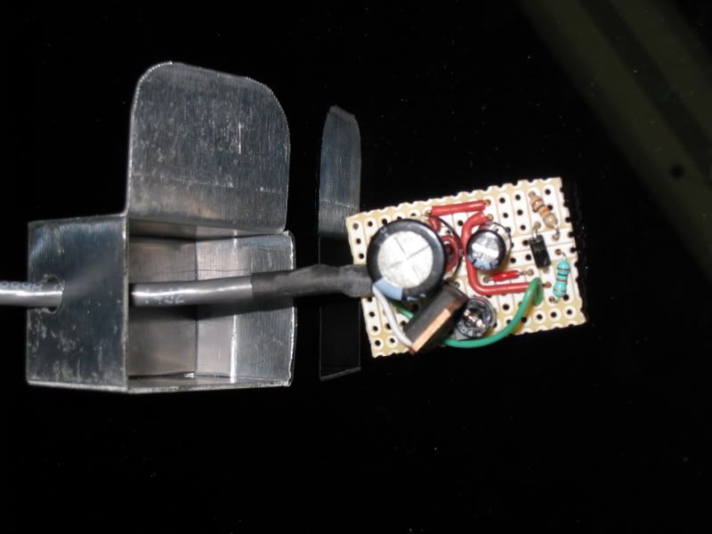 |
Reepicheep
| | Posted on Friday, October 03, 2008 - 10:43 am: |
|
Correct, capacitors in parallel act like resistors in series. So they are additive.
But thats a small difference for a fuzzy circuit, just 10%, so I think you could just drop the smaller capacitor and not notice much difference.
I just hand sketched a revised version of mine playing with an LM339. I'll throw together a schematic when I get back to my cad software at home and post it.
Electrolytic capacitors will self discharge pretty quickly, under a minute. Tantalum capacitors will hold a charge a lot longer.
I think your "R2" was supposed to decide how long a "warm start" is faster, but is that diode pointing the right way?
No matter, because you are using the electrolytic capacitor (all you will find in that high a capacitance) it works as it is.
I like your packaging... did you weld that up? Nice touch! |
H2owerker
| | Posted on Friday, October 03, 2008 - 05:27 pm: |
|
Unfortunately I haven't been able to get the tig at work set up to weld aluminum. So I think it will need a little JB Weld and paint to finish it. I'm going to machine an aluminum backing plate and bolt it in place. Sealed w/ a rubber gasket of coarse.
As far as the diode, I understand what they do, but I don't know what the one in this schematics purpose is. |
Reepicheep
| | Posted on Friday, October 03, 2008 - 07:12 pm: |
|
I think it is meant to be the path by which the capacitor discharges when the power is removed. It would be important if you were using a non leaky capacitor. It might even be useful in your current setup to keep the power from coming instantly back on in the event of a transient dropout. The timer would reset through the diode. |
H2owerker
| | Posted on Saturday, October 04, 2008 - 01:46 pm: |
|
What do you mean "transient dropout"? Like a drop in voltage? |
Reepicheep
| | Posted on Sunday, October 05, 2008 - 08:05 am: |
|
Yeah, like a loose battery cable or something. If its going "on off on off" like 8 times in 5 seconds or something, I would imagine that would be hard on the ballast, so it would be good to have the first "drop" just re-start the delay. |
H2owerker
| | Posted on Sunday, October 05, 2008 - 12:42 pm: |
|
Unfortunately it doesn't reset the timer that quickly. When I was setting the delay, the relay would chatter if I wasn't careful disconnecting the leads. |
|