| Author | Message | ||
Road_Thing |
RR & V2: During the time it took mine to fail completely, I replaced the starter solenoid! There's probably a reason why testing the relay is the very first item in the service manual section on the starting system... r-t | ||
Roadrunr |
Guess I will keep a relay in my pocket from now on just in case, but while poking around with my flashlight I may have found a bigger problem. The base gasket on the rear jug seeping oil!! DAMN FLASHLIGHTS! | ||
Roadrunr |
Sparky, that blade connector was the firs thing I checked. That came off about a year ago, almost had to call my wife to bring the truck before I found it "whew" woulda still been explaining what I was doing at the place I was at. "No sweetie, it just quit in front of crazy debbies house....Really!" | ||
Danblood |
I am looking for suggestions on how to beef up the charging system on a S3T 2002. I've added a set of motolights and a heated vest. Running them at the same time drains the battery. Given the weather here in Seattle (foggy and cold) I would really like run them both at the same time. | ||
Hootowl |
I lost ANOTHER speedo sensor this morning. That makes three in less than two months. I had a filter on the power wire too. I'm beginning to get a little bent about this. If it was reasonably priced, I'd just buy a hand full and move on. This is a $50 part. It shouldn't be. It's just a hall effect sensor. Nothing complicated. Anybody know if the tubers and XB/Blast! use different part numbers for the sensor? | ||
Reepicheep |
Awww crap. Were you running my filter? That sucks. Might want to check the wires for the sensor as well, that is one of two failure modes we have been seeing. If the wires check out, and the sensor is toast, and you were running my filter, I will draw out the schematic for an active filter using standard radio shack parts. Bill | ||
Hootowl |
Bill, I was using your filter. I think the part just sucks. What about a resistor in series? It would reduce the current and voltage to the device, but how much voltage does it have to output to the speedometer to make it work? Also, could the failure be because of too little input impedance at the speedo? The speedo could be blowing the sensor. A cap in series with the output will let the pulses pass, but block DC. What do you think? Jeff | ||
Reepicheep |
Here would be my rev 2 filter design. You probably want to build it on perfboard, avoid potentiometers (at least in the final version), and seal it up tight (when I was sure it was working I would probably just cake it with 100% silicone sealant, probably inside a small enclosure. This all goes on the V+ and ground wires. The signal wire is (as always) left unprotected. It does not protect against all failure modes. As designed, it will put out 10 volts. Adjust the R1/R2 ratio to change voltages. You won't find an exact value for the resistors I showed, but no big deal, you don't need exactly 10 volts either. Just get close. Make REALLY sure no joints or anything else on your existing setup did not fail, the failure mode would look very similiar. I did not build and test it... but it's a pretty straightforward design. Let me know if anyone tries it or has any questions. 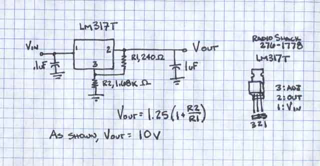 Bill | ||
Vasistass |
Did anybody know if we can put (easily) a XB9S Dashboard on a X1? I just want to know about wiring Thanks Vas! http://www.pitt-biull.com | ||
Hootowl |
Bill, I still think putting a cap in series with the output would help to isolate the sensor from the speedo. A simple RC coupling might do the trick. I have taken the sensor out of my Blast! and put it in my X1. They appear to be the same part. Same connector, same number on the tip of the sensor, with the exception of what appears to be a lot number. I wish I had taken the time to record the lot number (if that's indeed what it is) from my failed sensors. Has anyone had a sensor failure in their Blast!? Jeff | ||
99x1 |
I once worked on a BMW that was blowing ignition modules,turned out a spark plug cap was opening up only when hot, and causing 2000 volt spikes through the electrical system. If you have lost a couple of gear tooth sensors (gear tooth sensors are complex internally - hall effect sensors/magnet/microprocessor), hooking a portable scope up while running might be of some benefit. The LM317 is rated 0-125 degs C, and may do thermal shutdown if mounted near the engine? Putting a capacitor in series with the output may create other problems - oscillations and the potential of voltage doubling? John | ||
Reepicheep |
Jeff... A cap would do it, but would be tricky to size and would degrade the square wave coming from the sensor. It could probably be made to work, but if we are going to that level of trouble, why not just go the whole way and throw in optical isolators and really isolate the stupid thing once and for all. It might require a couple transistors as well, or an op amp, I will have to go back and look at the frequencies and voltages involved. We are still looking at less then $20 worth of parts, but are getting into a more complicated assembly. I can layout and make printed circuit boards if necessary. Before I go down that road, can you disect your failed sensor right down to where the wires go into the sending unit and make sure there was not a break / short in your wiring harness? Its a bear to pull apart the actual sensor, so thats not necessary, but eliminating broken wires as a possiblity would be a good thing. The reason I have not focused on the signal path in the past was because the filter can only put out what it is supplied. So if something is dying as a result of the signal path, it has to be coming in from elsewhere, or it has to be a result of the signal line being grounded somehow (assuming the sensor can't handle that, which would be a stupid way to design the sensor). So anyway, make sure the wires are not broken and post here. If they are not, I will be happy to put together a design for serious filtering of everything, with optical isolation of the signal path. Seems a bit silly, but should be able to solve the problem once and for all for less then half the cost of a replacement sensor. | ||
Hootowl |
Bill, I took the sensor down to parade rest. I didn't find any broken or shorted wires. That only leaves the little sensor in the tip as the culprit. As far as the cap in the output path, I was thinking it would take the DC load out of the equation, so whatever current the speedometer was drawing through the sensor would be reduced to a very small amount of displacement current. Just a cap wouldn't work I think. There'd have to a resistor to ground (RC coupling) Sizing of the cap would depend on the frequency of the pulses (obviously) so is there one pulse per revolution or many, with one pulse a different size? That's the configuration used in my truck. If it's one, then the filter would need to pass frequencies above 1KHz, which isn't hard to figure out. And if it's more, the 1K high pass would still work. I'm of the opinion that the failures are due to heat caused by an overcurrent condition. It may be that simply putting a few resistors in series with the power and output would do the trick, but I have no idea of the voltage requirements of the device, nor the input requirements of the speedometer. But I do know that reducing the current to the device and subsequently the voltage developed by the device will reduce the power dissipated by the sensor exponentially, (P=IE) and that would be (to quote Martha Stewart) "a good thing". I appreciate you designing a circuit to do the filtering. I haven't played with this stuff in years, and I never really got into design outside the classroom. Jeff | ||
Reepicheep |
I will start hunting parts and drawing up schematics. I don't think overcurrent is the problem, it is an FET device, and the input to the speedo is probably very high impedance already, though that is easy enough to test. Since it is outputting a square wave, power dissipation of the device is usually not an issue (power dissapated by the device is voltage across the device times current through the device... the great thing about a square wave switch is that its either all current and little voltage (device turned on) or little current and all voltage (device turned off)... either way very little power being dissapated). FET's are a lot more sensitive to high voltage spikes, which seems a lot more suspect to me. Guess I will be putting the o-scope back on the Cyclone. I'll try and keep the parts as "off the shelf radio shack" to make it possible for anyone to throw one together in an afternoon. Bill | ||
Hootowl |
Bill, As well as the field effect transistor, isn't there an inductor in there somewhere? There has to be something in there that would be effected by a magnetic field or there wouldn't be the need for a magnet. The actual sensor in the tip is a tiny little thing and while the FET may handle the current (pretty small channel though) the other components that are packaged in there would be subject to failure if there was indeed too much current. But, if it was an over current condition causing the failures, it would do it all the time. I think I have another problem that is causing the sensors to fail. What that may be, I don't know. If the input circuit to the speedometer is an op amp or an inverter/buffer, then yes, it would have a very high input impedance. Jeff | ||
Robr |
Hey Guys, Just an update on the speedo sensor on my '99 X1. The speedo would not register any speed until the bike had fully warmed up(10-15minutes). This went on over a period of maybe 200 miles until the sensor finally quit working altogether at 3600 miles. I replaced the sensor with a new one. This was before there was an updated part number. I moved the +12v lead for the sensor out of the ignition circuit and spliced it into the lighting circuit. The X1 now has 9887 miles and the speedo sensor(knock on wood), is still functioning. Also to be taken into account was the addition of a large Lockhart oil cooler installed around 4000 miles, this dropped the oil temperature 30-40 degrees F (bike runs nice and cool at around 200F now). This could pertain if the problem is heat related which my initial symptoms may point to. Rob. | ||
Hootowl |
Rob, I think putting the sensor in the light circuit is going to be my next move. I have never experienced an intermittent sensor failure like you described. Mine just go out. I also have over 37K miles on mine, if that makes any difference. How do you know if you have the updated part number? Maybe I'm getting the old ones from the back of the shelf? | ||
Bluzm2 |
Bill, If the Anony from the GDB is correct (here's the quote): "Couldn�t post as anonymous on the �Electrical � Starter, Lights, Switches, and Gages� string. Reepicheep is on the right track. Try reducing close to 5V rather than 10V though. XB9S sensor is powered from the ECM at 5V rather than the ignition circuit at 12V. No need to mess with the signal line. The failures may not all be electronic, some could be mechanical failures internal to the sensor with the current parts. Expect an updated sensor to be available in mid January 03, but dealers may have old stock in inventory." If Anony is correct, a simple 7805 5V regulator would do the trick. Slap a filter cap on the output, seal it up and you're done. I'd have to run the math part for power for a 5 volt drop but it should run pretty cool. Don't think it should need a heat sink. What do you think? Sounds like you have done the theory thing more recently than I. Brad | ||
Reepicheep |
Use the LM317T as in the schematic above, but instead of putting in a 1.68k ohm resistor for R2, use a 720 ohm resistor (or thereabouts). I just use the LM317t because it is adaptable to just about any step down voltage, and is available off the shelf at most radio shacks. I keep a spare laying around for whenever I need to tweak a DC adapter. Brad.. the LM7805 would be an excellent choice, better then the chip I listed now that we know we want 5 volts. The whole circuit would have only one other external component, very cool. If you can find it, use it instead. Next time I am out, I will check Radio Shack and see if they stock them. I think they do (or some similar fixed 5v chip). It is probably just the same as the 317T I am using but has the internal fixed resistor network instead of external pins. (and fewer joints == much better on a 45 degree long stroke twin  Post if anyone wants a schematic or pinout using the 7805. I will see what fixed 5v regs are at Radio Shack (who I only recommend as they are easy to find). The 317t is good for 15 watts without a heatsink (so they claim). Looks like the 7805 has the same packaging, which means it probably dissipates about the same power (Sounds a little high to me to be running without a heatsink). Regardless, that would make like 7 amps, which is probably 20 times more power then this thing draws. So I would not be concerned about power dissipation on either of the chips in this application. You could probably pot the whole thing in silicone in a film canister or something and be fine. Just don't cable tie it to the exhaust header or anything. Thanks again Anony... this is a silly problem to not have put behind us. | ||
Bluzm2 |
Bill, I just checked Radio Hack's web catalog, no 7805's, just the 317. They used to carry them a few years back but I suppose the demise of the workshop hacker led them to drop most of their raw components. Too bad, I still need stuff once in a while. Fortunately I have lots of other sources. I would love to find a source for the male and female Deuech (sp?) connectors. I would make up a bunch of the regulators and sell the buggers a cost just to save folks the hassle of a burned out speedo sensor. Just plug the bugger in and be done with the whole thing. Brad | ||
Ccryder |
Hey Brad: It is really strange that out of my 2 FI Buells with over 60k+ miles that I have not had one speedo sensor issue (knock on wood, throw salt over my shoulder....). Anyway if you can find the P/N's for the connectors and male/female pins, I bet I can ID a source. After that I would have to take you up on your offer. Happy New Year To All, Thanks For Another Buelltiful Year. Neil S. | ||
Robr |
Hootowl, The speedo sensor for tube frames was updated to part #74431-01Y, back in Dec.2001. Rob | ||
Bluzm2 |
Robr, It didn't fix the problem. I smoked one of them also. Same sensor, just a shorter lead. It's the same as the Blast sensor. Brad | ||
Hootowl |
I found a 7805 at the local radio shack, put it in a box under the battery. Seems to work, but for how long? Time will tell. Thanks everyone for all your help. Hopefully this will solve my problem. Jeff | ||
99x1 |
Possibly rather then a 7805, the LM2930 could be used. "Designed originally for automotive applications, the LM2930 and all regulated circuitry are protected from reverse battery installations or 2 battery jumps. During line transients, such as a load dump (40V) when the input voltage to the regulator can momentarily exceed the specified maximum operating voltage, the regulator will automatically shut down to protect both internal circuits and the load." It is available in 5 or 8 volt outputs from DigiKey for $1.58. I think the ultimate solution would be for someone to make a speedo recalibrator, like the S&S, but with power filtering built in... John | ||
Hootowl |
Rob, I've let the smoke out of three of those in the past three months. (All electronic equipment operates on smoke. You let the smoke out, they don't work anymore.) | ||
Bluzm2 |
Hoot, I'm stealing that one!!!! LMAO Brad | ||
Robr |
I guess I was thinking wishfully. Hopefully(wishfull thinking again), in Jan.'03 there will be an updated sensor for the tubed frames as well as the XBs. Rob | ||
Hootowl |
Amen | ||
Mikej |
Someone posted a pic of an S1 with the new XB9S headlights, then someone else mentioned the headlight assembly is fairly inexpensive, this got me to thinking. Has anyone identified what headlights are used on the XB9S? If so, or if not, does anyone know if a dual-element headlight is available in that size format with will hold up to bike use? Might be time to get a sheet of plexiglas and put it in the oven and start forming some plastic and do a little cosmetic surgery on the M2. |