G oog le BadWeB | Login/out | Topics | Search | Custodians | Register | Edit Profile

Buell Forum » Knowledge Vault (tech, parts, apparel, & accessories topics) » Engine » Fuel System: EFI/DDFI, Carb., Filter, Pump, Tank, Filler-Cap, Fuel » Archive through September 11, 2006 » Air/fuel gauge test « Previous Next »

Written by Al Lighton for Battle2win magazine

So, you bought a cool aftermarket muffler with the thunderous sound to die for, and a high-flow air intake system that doesn’t look like a wart on the side of your carbureted Buell. Everything you’ve read says that the combo is good for 10 or more extra ponies once the bike is dialed in. But there’s the rub. You don’t have access to a dyno, and even if you did, you aren’t convinced you want to pay Dyno Dans $75 per hour to dyno tune your bike with each change of components, weather, and altitude. So you resort to anecdotal jetting based on web comments from someone that has a similar muffler or intake, and figure you’ll just compensate a jet size or two for the fact that they live at four times your altitude. Or maybe you figure that you can read the plugs and get it close enough. You’re sure it’s pulling harder than it did before, after $500 of parts and 4 hours of carb/jet swapping, it must! If only there was a better way of ensuring the jetting really is optimized….

This article describes one alternative to using that expensive dyno tuning service for dialing in the jetting for peak ponies. Air/Fuel (A/F) ratio meters that use O2 sensors in the exhaust are common, and there are lots of anecdotal stories on the web of folks that have used them “successfully” on their Saturn motor or Honda Fuel Injected (FI) autocross car. But there isn’t much out there that confirms that a cost effective meter can be used to accurately predict peak WOT horsepower when tuning a carbureted motorcycle engine. In fact, even FI vehicles don’t use the O2 sensor for getting peak power at WOT, they depend only upon the engine mapping done at the factory. Since there wasn’t enough empirical evidence behind the readily available info on using such a system, I set out to determine if an A/F ratio meter could be used to accurately tune our hot rod sporty engines for peak power.

Theoretically speaking…
An oxygen sensor works by outputting 0 to 1 Volt DC based on the amount of residual oxygen sensed in the exhaust gas. A richer mixture consumes more of the oxygen and causes a higher voltage output, which is read on a specialized voltmeter. The stoichiometric mixture, where the A/F ratio is optimized, is approximately 14.7:1 (i.e., a mass of air of 14.7 to a mass of fuel of 1) for gasoline. This ratio is where the engine will get the best fuel economy and have lowest emissions. But it’s not the ratio that will provide maximum power, which is obtained somewhere around 12.8:1 give or take a few points (depending upon fuel composition). The O2 sensors are highly non-linear, as shown in Figure 1. They are optimized for controlling FI motors where the computer controlled injectors keep the ratio at 14.7:1 by varying injector duration to maximize the number of 0.45-volt crossings, which happens many times per second. The exact voltage output by the O2 sensor is not meaningful for determining an exact rich A/F ratio, since different sensors, and even the same sensor at different temperatures, have different output voltages at the knee of the curve. However, while the sensor/meter can’t tell us exactly what voltage equals 12.8:1, the max power should occur just after the knee of the response curve. The theory is that that the knee of the curve should be able to be determined by observing the meter ballistics as the meter transitions from a very bouncy reading to a somewhat steady reading, and that tuning to approximately 12.8:1 should be possible if approached from the lean side. There was some uncertainty as to whether the O2 sensor would accurately sense just the burned mixture given the amount of valve overlap that exists in an S1 with Lightning cams. So off we went to the dyno to confirm the theory and determine if the sensors accurately indicated mixture and therefore predict peak power.


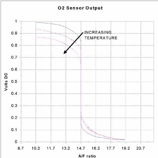
Figure 1. Oxygen Sensor response
Testing..Testing
The first step for testing an A/F meter is to modify the header to mount an unheated O2 sensor a few inches from the rear exhaust port. Look at any of the 99 or later FI Buells for how they are installed. I fabricated a similar fitting from stainless rod and had it welded to my stock S1W header as shown in Figure 2.


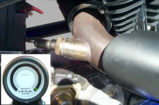
Figure 2- Oxygen Sensor fitting, Inset is Air/Fuel Ratio Meter

The first question to be answered is if the modification of the pipe hurts peak power and makes the measurement meaningless. So we did baseline pulls on a ’96 T-stormed S1 with a Mikuni HSR42, a ‘98 S1W header, and a V&H muffler. Maximum power was obtained with a 157.5 jet (note: it was a 45-50°F, rainy day at 5400 Feet altitude), with a 160 jet giving virtually the same readings. We then swapped the header with the modified S1W header and did comparison runs with the same 157.5 jet with the fitting capped and with an O2 Sensor installed. The results of those runs are shown in Figure 3. It is clear that power was not degraded, and was in fact higher, likely due to small differences between the two headers. Convinced that the rest of the testing could be meaningful, we now set out to correlate power with meter readings.


Figure 3. Stock Header, Modified Header with Plug, Modified Header with sensor

An Autometer A/F meter with 20 LEDs (5 red, 10 yellow, and 7 green), each indicating 0.05 VDC was connected to the O2 sensor. A series of dyno pulls were performed with first richer and then leaner main jets installed. Figure 4 shows the results of those dyno runs and meter readings. With each run, the meter reads full rich as the motor is started and the sensor comes up to operating temperature. The first run was with the same 157.5 jet that indicated peak power in the previous baseline runs. As the sensor came up to temperature, the meter was bouncing in the top 3 of the yellow and the first green LEDs through the lower RPM range of the runs and steadily lit the second green LED and flickered the third LED through the upper engine revs of interest. Going richer to 160 flickered the first green LED green through the lower RPMs and solidly lit the third green LED as RPMs increased to redline. The 162.5 jet gave a similar result, but lit the fourth green LED solidly as the RPMs increased. Going leaner to a 155 jet caused the meter to bounce in the top 4 yellow LEDs and just barely lit the second green LED near redline. A 152.5 jet caused the meter to bounce over the full stoichiometric yellow LED range, rarely lighting either the green or red. Lastly, a 150 jet was put in and the red lean LEDs stayed on through the first 1/2 of the RPM range and slowly bounced into the stoichiometric range as peak RPM was obtained. The meter readings were very bouncy as expected through the stoichiometric range, but were quite steady as the display moved through the knees on both the lean and rich end of the readings. These results confirmed the theoretical output response and showed that if tuned so that the meter displayed that it was transitioning through the knee of the curve, from a bouncing flickering reading to steadily lit rich readings, optimum jetting could be APPROXIMATELY obtained. It was not obvious from the readings whether the 157.5 jet or the 160 jet was optimum. However, it should be noted that the dyno is not precise for determining this either. For example, some runs with the 160 jet had higher power than some runs with the 157.5 jet. It takes some “eye-averaging” of several plots from those pulls to select the jetting that gave the best performance, and the difference was less than one horsepower either way.


Figure 4. Different Jet Dyno Curves and Their Corresponding Meter Readings

One more test was needed to determine if this would be an acceptable tuning method. If the meter indicated substantially different readings as ignition timing was varied, then one wouldn’t know to change the timing or the jets for any given reading to get the right meter reading and optimum performance. This test wasn’t run on the dyno. A baseline blast down a straight road at WOT was performed with the timing at the nominal setting. It was then moved two ticks (10 degrees) advanced and retarded, and similar WOT runs performed. No significant change in meter reading resulted in either case, though there may have been a very slight bias towards richer indications as the timing was advanced

Does it work?
The conclusion is that for this mildly tuned street motor with mild cam overlap, the O2 sensor and A/F meter combo is reasonably accurate for selecting the jetting for peak power. But this setup allows for more than tuning for peak power. I didn’t have an eddy brake dyno that would have allowed steady state runs across partial throttle and variable loads, nor did I have a metered fuel and air delivery system for correlating the actual A/F ratio against the indicated readings. But it is a relatively small leap of faith to assume that if the system is accurately predicting peak power, it can also be used to optimize the pilot and needle jetting at partial throttle to keep the bike in the stoichiometric range. A properly calibrated across-the-midrange carburetor will maximize fuel economy without penalty, since any demand for more power is always just a twist of the wrist away. Subsequent road testing of my S1W with the meter installed has resulted in rejetting of the pilot and needle settings in my carb to leaner settings. My mileage has increased from 45 mpg to 51 mpg in normal usage, with no negative effects on driveablity or performance

For many of us, neither our bikes nor the environment we run them in is static. With an A/F meter connected, a new air cleaner, a change of the exhaust baffles or packing, or the change from summer to winter doesn’t mean a trip to the dyno for another jetting change. And an Air/Fuel meter is a lot more portable than a dyno.

Acknowledgements
I’d like to acknowledge Aaron and Susan Wilson for providing the facilities, motorcycle, and dyno expertise to perform this testing, and Jerome Chappellaz for his inspiration for performing this test. Jerome’s road testing of an A/F meter and his results posted on Badweb led to the questions that this article hopefully answers.


Battle Gear
K&N Unheated O2 Sensor- (includes plug and unsuitable weld-on fitting) - 85-2438, $59.95
(see http://www.knpowersports.com/docs/air_fuel_monitors.html for K&B Tech tips)
Buell Unheated O2 Sensor- 65970-99Y, $24.10
Beck Arnley Unheated O2 Sensor - 156-8100
Bosch Unheated O2 Sensor - 12014
AutoMeter Phantom A/F meter- 5775, $53.95 (see http://www.autometer.com/hp/index.html for AutoMeter tech tips)
Autometer Black Meter mounting cup- 2204, $12.95
Weld Fitting-Buell style fitting not commercially available, fabricate from stainless bar stock.

Author Message
Top of pagePrevious messageNext messageBottom of page Link to this message

Aaron
Posted on Friday, October 11, 2002 - 12:47 am:   Edit Post Delete Post View Post/Check IP Print Post    Move Post (Custodian/Admin Only) Ban Poster IP (Custodian/Admin only)

Al, if you'd like any changes to the above, ping me
Top of pagePrevious messageNext messageBottom of page Link to this message

Al_Lighton
Posted on Friday, October 11, 2002 - 03:11 am:   Edit Post Delete Post View Post/Check IP Print Post    Move Post (Custodian/Admin Only) Ban Poster IP (Custodian/Admin only)

Cool, Aaron, it came out well on the pages here. Looks as I wrote it. If anyone out there in badweb land has any corrections/clarifications, I'm happy to change it to ensure the most accuracy. Don't want to spread any false info if I screwed up anywhere. Any one else using a similar setup, if you want to comment on your experiences, all the better.

And like the article says, thanks Aaron for letting me play.

Al
Top of pagePrevious messageNext messageBottom of page Link to this message

Reepicheep
Posted on Friday, October 11, 2002 - 08:32 am:   Edit Post Delete Post View Post/Check IP Print Post    Move Post (Custodian/Admin Only) Ban Poster IP (Custodian/Admin only)

Al... Very cool! You are tempting me... a couple questions...

I assume this testing has to be done under load. I.E. you cant just rev the engine no load in the driveway and annoy the neighbors. I as this as I have an oscillascope, which I think would give a much better picture of what is going on.

If I don't want to weld to the header, is there a heated sensor I could slip in the tail pipe? I guess this may not be applicable if I have to test under load.

I guess what you are saying above is that it is a decent way to get the jetting dialed in, but will not measure the quality of the timing adjustment.

Those jets are much smaller then I expected... I am running a 200 main (from the factory) for our location (about 800 feet above sea level).
Top of pagePrevious messageNext messageBottom of page Link to this message

X1glider
Posted on Friday, October 11, 2002 - 08:50 am:   Edit Post Delete Post View Post/Check IP Print Post    Move Post (Custodian/Admin Only) Ban Poster IP (Custodian/Admin only)

Alright, about time there's something worth reading around here. "Great job" to all those involved in putting the article together.
Top of pagePrevious messageNext messageBottom of page Link to this message

Al_Lighton
Posted on Friday, October 11, 2002 - 08:52 am:   Edit Post Delete Post View Post/Check IP Print Post    Move Post (Custodian/Admin Only) Ban Poster IP (Custodian/Admin only)

Bill,
The tests for setting the main jet are all WOT, so yea, I think there better be a load unless you want to fetch your piston from the neighbor's roof!

There are heated sensors that are otherwise identical in their response curves. But I'm not sure how valid the tests would be if they're not just putting their tip into the stream somewhere. I don't think you can shove the WHOLE sensor into the pipe and expect that the exhaust flow is the same as when it's removed. I had that concern even with putting the tip in, thus the first part of the test to ensure that we didn't hurt power by making the measurement. That said, I think the sensor that Aaron now uses with his dyno shoves into the pipe, but I think it's real long and skinny. It's also a linear response wideband sensor that costs a couple thousand bucks (I think)!!

Those jets are Mikuni jets. So the numbers are different than what you'd use with a Keihin (sp?). Mikuni's are great for this kind of testing, you can change the main jet in about two minutes. I was amazed that Aaron would just remove the bottom jet acces plug and drop a bowlful of gas right onto the very hot header. But he does it all the time, it won't flash.
Top of pagePrevious messageNext messageBottom of page Link to this message

Sarodude
Posted on Friday, October 11, 2002 - 10:05 am:   Edit Post Delete Post View Post/Check IP Print Post    Move Post (Custodian/Admin Only) Ban Poster IP (Custodian/Admin only)

Al-

Great stuff. I do take some issue with the statement regarding stoichiometric a/f providing the best mileage. Lean Burn gasoline engines have been toyed with and mass produced (at least by Honda) in the interests of fuel efficiency.

Minor point as those were very specifically developed motors. Great article worthy of a great magazine. I'm glad it surfaced here instead of disappearing.

-Saro
Top of pagePrevious messageNext messageBottom of page Link to this message

Jerome
Posted on Friday, October 11, 2002 - 03:59 pm:   Edit Post Delete Post View Post/Check IP Print Post    Move Post (Custodian/Admin Only) Ban Poster IP (Custodian/Admin only)

Al : really great job ! Thumbs-up and congratulations ! It's so nice to see dyno tests combined with A/F ratio reading on the Autometer gauge ! Too bad Battle2Win disappears before this great article gets published. I hope that it will stay visible within the BWB board and that it will convince some other carburated-Buell owners to install this great and relatively cheap tool. Mine is still on-board and used to keep my Mikuni in good tuning conditions.
Top of pagePrevious messageNext messageBottom of page Link to this message

Shotgun
Posted on Friday, October 11, 2002 - 09:40 pm:   Edit Post Delete Post View Post/Check IP Print Post    Move Post (Custodian/Admin Only) Ban Poster IP (Custodian/Admin only)

Great article Al. If anybueller would like to borrow my Nordskag A/F guage, O2 sensor, extra bung, hole saw, let me know. Pay to ship it both ways. Mine is a heated sensor, set up to plug into any SAE outlet like those used for battery chargers or heated clothing outlets. A muffler shop can install the bung. They usually have extra Bosch universal bungs on hand anyway. Ping me if you're interested.
Top of pagePrevious messageNext messageBottom of page Link to this message

Scot
Posted on Monday, October 14, 2002 - 02:05 am:   Edit Post Delete Post View Post/Check IP Print Post    Move Post (Custodian/Admin Only) Ban Poster IP (Custodian/Admin only)

Heres a picture of a a/f gauge that I am making. It is a billet display that will wrap partially around my tachometer. This is my first attempt at a milling project. I have a vert. mill I'm trying to teach myself how to use.
Top of pagePrevious messageNext messageBottom of page Link to this message

Bomber
Posted on Monday, October 14, 2002 - 02:40 pm:   Edit Post Delete Post View Post/Check IP Print Post    Move Post (Custodian/Admin Only) Ban Poster IP (Custodian/Admin only)

just a data pooint . . .I met a rider with an autometer sensor (I believe) who said that running gasahol ate up sensors at a high rate of speed . . . . with the spread of higher percentages of corn in our gas, this could represent a problem . . . .

I hasten to add that I have no direct experience with this, just reporting one person's data
Top of pagePrevious messageNext messageBottom of page Link to this message

Al_Lighton
Posted on Monday, October 14, 2002 - 04:15 pm:   Edit Post Delete Post View Post/Check IP Print Post    Move Post (Custodian/Admin Only) Ban Poster IP (Custodian/Admin only)

It would in fact represent such a problem that I doubt it can be true. These sensors (in different variants all fundamentally based on the same technologies) are in virtually every car made any more. It would seem incomprehensible that there would be commercial grade lead-free gasoline that is capable of destroying these sensors. I could be wrong, but it just seems very unlikely. The gasloine company would get a HUGE lawsuit.

Al
Top of pagePrevious messageNext messageBottom of page Link to this message

Ocbueller
Posted on Monday, October 14, 2002 - 07:12 pm:   Edit Post Delete Post View Post/Check IP Print Post    Move Post (Custodian/Admin Only) Ban Poster IP (Custodian/Admin only)

Scot,
Nice work, keep up the posts with the finished product.
SteveH
Top of pagePrevious messageNext messageBottom of page Link to this message

Rick_A
Posted on Monday, October 14, 2002 - 10:53 pm:   Edit Post Delete Post View Post/Check IP Print Post    Move Post (Custodian/Admin Only) Ban Poster IP (Custodian/Admin only)

Great write-up! It's got my wheels turnin'
Top of pagePrevious messageNext messageBottom of page Link to this message

Bomber
Posted on Tuesday, October 15, 2002 - 12:46 pm:   Edit Post Delete Post View Post/Check IP Print Post    Move Post (Custodian/Admin Only) Ban Poster IP (Custodian/Admin only)

Al . . .. .no argument from me . . .. just reporting one guy's experience with one brand of sensor . . . . .
Top of pagePrevious messageNext messageBottom of page Link to this message

Kucenskm
Posted on Wednesday, October 16, 2002 - 04:07 pm:   Edit Post Delete Post View Post/Check IP Print Post    Move Post (Custodian/Admin Only) Ban Poster IP (Custodian/Admin only)

The article mentions several different O2 sensors. What are the differences between these sensors aside from the price? Which sensor was used throughout these tests?
Top of pagePrevious messageNext messageBottom of page Link to this message

Al_Lighton
Posted on Wednesday, October 16, 2002 - 08:16 pm:   Edit Post Delete Post View Post/Check IP Print Post    Move Post (Custodian/Admin Only) Ban Poster IP (Custodian/Admin only)

I believe that the only significant difference in the sensors is minor physical geometry and possibly connectors. All of them have been successfully used on Buell FI bikes. They should all have essentially the same non-linear response curves around the stoichiometric point, but may have minor variations on the absolute voltage of the knee of the curve. Bottom line, any of them will work, if you remember that you are looking for the meter ballistics to determine the knee, not the absolute voltage.

I used the K&N sensor for the tests, which looks identical to the stock buell sensor physically. I'm sure K&N doesn't make it, it's just repackaged and marked up. I bought it to get the fitting, but the fitting isn't really suitable for this application, it is short and straight and puts way too much sensor protrucion into the pipe. I don't know how much that would've hurt power, but as the article says, the fitting I built didn't hurt power at all.

Al
Top of pagePrevious messageNext messageBottom of page Link to this message

Scot
Posted on Thursday, October 17, 2002 - 01:28 am:   Edit Post Delete Post View Post/Check IP Print Post    Move Post (Custodian/Admin Only) Ban Poster IP (Custodian/Admin only)

There is also the 2 wire vs. 4 wire O2 sensor. The 4 wire has a heater element in it that I believe gets the sensor up to operating temperature quickly.
Top of pagePrevious messageNext messageBottom of page Link to this message

Al_Lighton
Posted on Thursday, October 17, 2002 - 09:18 am:   Edit Post Delete Post View Post/Check IP Print Post    Move Post (Custodian/Admin Only) Ban Poster IP (Custodian/Admin only)

Actually, I think there 1 wire, two wire, and 4 wire sensors. I'm sure of 1 and 4, and THINK I remember reading about 2.

All of the ones listed in the article are one wire sensors, just like Buell uses for their FI system. The return is thru the body to ground, just like a spark plug. I suspect that two wire sensors provide a wired return, and that 4 wire sensors are heated 2 wire sensors with a hot and return wire for the heater element. But all that's just a guess. I've only physically held a 1 wire sensor in my hand.

The heated sensors are needed if you remote the sensor way down the pipe to the collector. I'd read before the test that idling for extended periods would cause the unheated sensor to cool and give false readings, but that hasn't been my experience. Buells seem to do just fine with their unheated sensors on the FI bikes. The sensor is up to temp and providing consistent readings within 20-30 seconds of starting the bike.

Al
Top of pagePrevious messageNext messageBottom of page Link to this message

Blake
Posted on Monday, March 10, 2003 - 03:54 pm:   Edit Post Delete Post View Post/Check IP Print Post    Move Post (Custodian/Admin Only) Ban Poster IP (Custodian/Admin only)

Great article Al!

Something came up recently in another discussion that has me thinking. With the sensor on only one main header pipe we are only getting information for that particular cylinder, the rear cylinder in your test case and the stock Buell DDFI case. As much as I hate stringing wires all over a bike, would it not be much better, given the risk of intake leaks, to either put a heated sensor downstream of the collector, or to install a 2nd sensor on the front header pipe?
Top of pagePrevious messageNext messageBottom of page Link to this message

Peter
Posted on Monday, March 10, 2003 - 04:32 pm:   Edit Post Delete Post View Post/Check IP Print Post    Move Post (Custodian/Admin Only) Ban Poster IP (Custodian/Admin only)

There are 1,2,3 and 4 wire sensors available. I use a 3 wire, which means the sensor earth is through the header. 3 and 4 are heated. 2 and 4 have a separate wire for the sensor earth.

The problem with setting up stoichometric combustion with the sensor in the collector or later, is that the rear cylinder normally runs leaner. If the average between the two cylinders is perfect, the rear cylinder is then running the risk of a too lean condition.

PPiA
Top of pagePrevious messageNext messageBottom of page Link to this message

Blake
Posted on Monday, March 10, 2003 - 05:30 pm:   Edit Post Delete Post View Post/Check IP Print Post    Move Post (Custodian/Admin Only) Ban Poster IP (Custodian/Admin only)

As long as we know that, we can adjust mapping or jetting accordingly, right? But if the front cylinder develops an intake seal leak and we only have a sensor on the rear cylinder, it goes completely unaddressed. Maybe two sensors with a switch to the readout panel would be the best diagnostic tool for a carbureted bike?
Top of pagePrevious messageNext messageBottom of page Link to this message

Blake
Posted on Monday, March 10, 2003 - 05:33 pm:   Edit Post Delete Post View Post/Check IP Print Post    Move Post (Custodian/Admin Only) Ban Poster IP (Custodian/Admin only)

Besides, we're not talking about stoichiometric, we're talking about max power. Silly Ozzie. :p
Top of pagePrevious messageNext messageBottom of page Link to this message

Rempss
Posted on Monday, March 10, 2003 - 08:56 pm:   Edit Post Delete Post View Post/Check IP Print Post    Move Post (Custodian/Admin Only) Ban Poster IP (Custodian/Admin only)

I am putting an O2 sensor in the mirror location of the rear in the front pipe to log that information. Running 4 wire SMP brand O2's.

I have been prompted to do this after reading a passage in the Big Twin HP Guide by D.W. Denish. Oddly enough he states that the front cylinder is more apt to run lean than the rear due to the uneven timing between intake pulses in the 45 degree V-twin. I don't have the book in front of me right now but I believe his term is either "normally" or "usually" this is the case. My plugs have confirmed this, but the O2 will do a better job.

I need to get to the bottom of this.

Jeff
Top of pagePrevious messageNext messageBottom of page Link to this message

Peter
Posted on Tuesday, March 11, 2003 - 02:25 am:   Edit Post Delete Post View Post/Check IP Print Post    Move Post (Custodian/Admin Only) Ban Poster IP (Custodian/Admin only)

Blake,

M2 location.
1

S1 location.
2

However, I am making a new header for the S1 at the moment and will also be doing the same as Jeff and fitting one at each head. I also have an EGT sensor after the turbo to monitor the combined effects.

Jeff,
He could be right.

PPiA
Top of pagePrevious messageNext messageBottom of page Link to this message

Joelber
Posted on Sunday, November 09, 2003 - 04:01 pm:   Edit Post Delete Post View Post/Check IP Print Post    Move Post (Custodian/Admin Only) Ban Poster IP (Custodian/Admin only)

A couple of dumb questions?? Does the xr2 forcewinder intake system ad any hp?? or is it just for looks?? If you add it: is it a good idea to take the air scoop off the other side?? I have a 99 x1--race kit in already
Top of pagePrevious messageNext messageBottom of page Link to this message

Ryker77
Posted on Friday, June 10, 2005 - 03:08 pm:   Edit Post Delete Post View Post/Check IP Print Post    Move Post (Custodian/Admin Only) Ban Poster IP (Custodian/Admin only)

Does the Hipo 02's sensor for the pcIII work with this guage system? I would assume that the hipo 02 sensor is a narrow band sensor..


and a BIG thanks for posting this great article!
Top of pagePrevious messageNext messageBottom of page Link to this message

Ryker77
Posted on Sunday, June 19, 2005 - 11:31 am:   Edit Post Delete Post View Post/Check IP Print Post    Move Post (Custodian/Admin Only) Ban Poster IP (Custodian/Admin only)

OK. I've got the A/F gauge installed and almost wired up. Just need to know which wire on the 4-wire 02 sensor to use???

With the o2 sensor unplugged one wire looks like it should be the sensor wire. But when I connect the PCIII that same wire goes to 12v. So I tried the purple wire and it reads .512 with the switch on and engine not running. With the engine running the purple wire (PCIII harness) will increase to .545+/-.

Has anybody wired up an A/F gauge with the 4 wire o2 sensor??

02 x1 with PCIII
Top of pagePrevious messageNext messageBottom of page Link to this message

Ryker77
Posted on Sunday, June 19, 2005 - 12:33 pm:   Edit Post Delete Post View Post/Check IP Print Post    Move Post (Custodian/Admin Only) Ban Poster IP (Custodian/Admin only)

Well I tapped the purple wire and got it right. At idle my x1 will bounce around toward the rich section then as it lopes it will flash lean just a quick flash.

I think the bike needs it TPS reset and/or replaced and probably the plugs since it has been running very rich.
Top of pagePrevious messageNext messageBottom of page Link to this message

Blake
Posted on Friday, September 18, 2009 - 02:39 am:   Edit Post Delete Post View Post/Check IP Print Post    Move Post (Custodian/Admin Only) Ban Poster IP (Custodian/Admin only)

Great article. Need to bookmark.
« Previous Next »

Add Your Message Here
Post:
Bold text Italics Underline Create a hyperlink Insert a clipart image

Username: Posting Information:
This is a private posting area. Only registered users and custodians may post messages here.
Password:
Options: Post as "Anonymous" (Valid reason required. Abusers will be exposed. If unsure, ask.)
Enable HTML code in message
Automatically activate URLs in message
Action:

Topics | Last Day | Tree View | Search | User List | Help/Instructions | Rules | Program Credits Administration