| Author | Message | ||
Ericz |
Here are a few pics of the recent little mods I have done recently. Things are going back together slowly while I wait for my forged CP pistons with thermal coatings on the tops and an anti friction coating on the skirts Indicator LED's recessed into the handlebar cross brace. From left to right they are a blinking red LED for low oil pressure, a yellow LED for low fuel, a green LED for Neutral, and a normal(non-blinking) red LED on the right for check engine. I used an 8 pin Deutsch DTM series connector for all of the led and gauge wiring plug. It replaces the factory gauge harness. I stripped the factory wiring harness of all of the wires I am not using anymore (like speedo)and moved any wiring I had added into the factory harness so that everything is neat and clean. 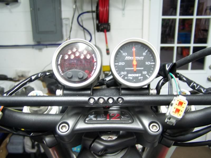 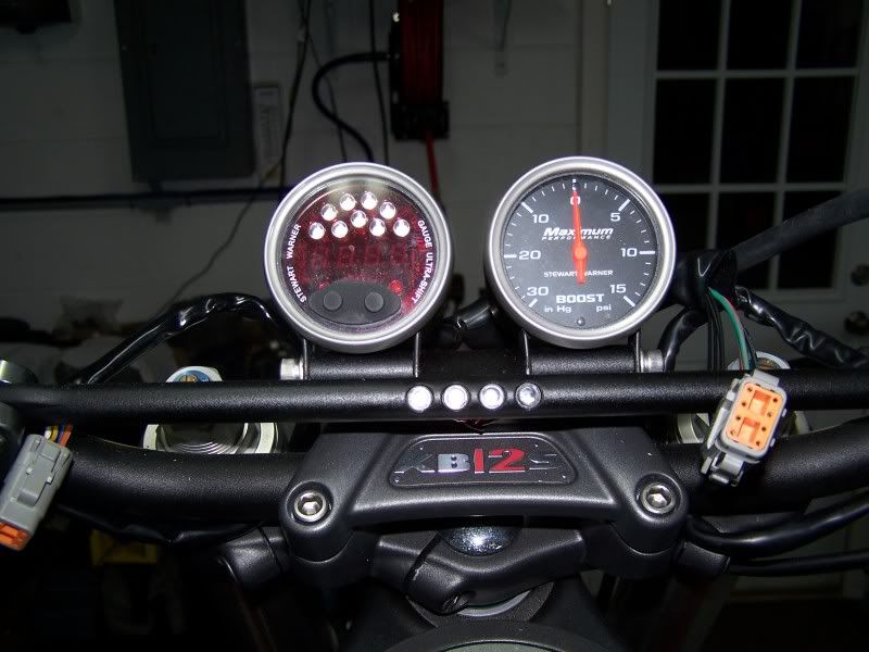 I also did some port work on the cylinder heads. It's my first time porting H-D/Buell heads but I am very happy with the results. I can't wait to see what happens on the dyno! 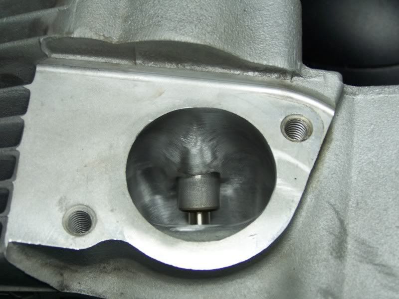 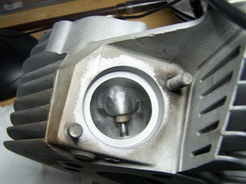 I got some DieselMoto aluminum subframe spacers. I was running some small spacers I made up to lift the battery tray up enough to clear the new shock angle with the long swingarm. I am welding the spacers to the stock subframe rails and then smoothing everything out. Even welding up the factory bolt hole, too. The rails will look smooth and won't have the bolt hole. 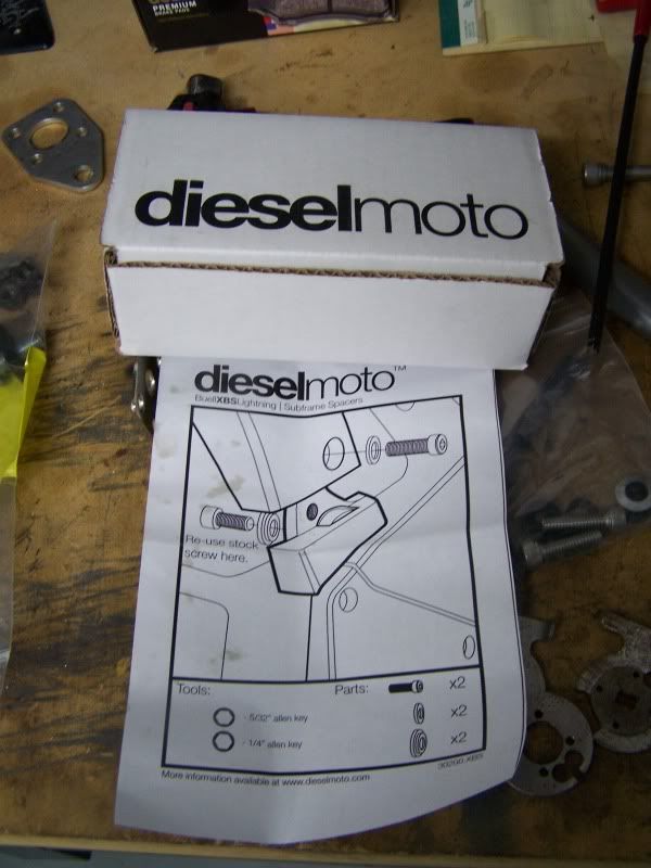 And here are a few shots of the latest oil scavenge pump. The last shots were dark and unclear when it was mounted to the bike. It's an EngineGear pump that I modified by adding a ball check valve in the longer of the two passages. That's the end that returns the oil to the swingarm. I cut of the factory welded on bracket and welded on a new bracket that bolts to the rear of the primary cover. 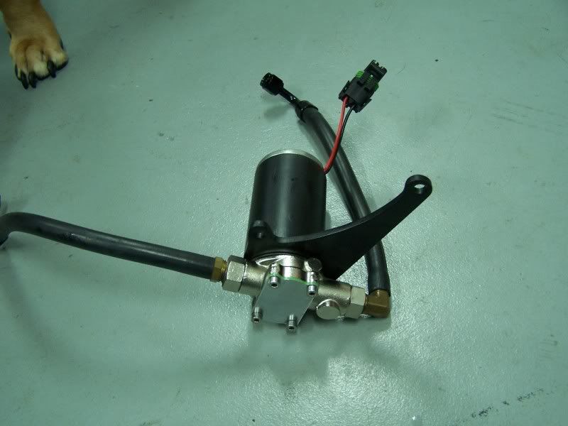 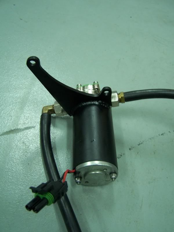 | ||
Gunut75 |
Got some good stuff there! Nice work.  | ||
Levi |
That's some nice work. Well done man. | ||
Firebolt32 |
About time to have that dog's nails clipped. | ||
Jbolt |
He's doing port work on his own heads and your giving him crap about his dogs nails. Give'm a break. Keep up the good work Eric. How much do you think all this is going to improve, with the turbo? | ||
Ericz |
Firebolt32-- Haha! Actually, My dog is a Long-clawed East Sylvanian Black Sunnenhund. Plus, She prefers them that length  Jbolt-- I am looking to see 200hp and maybe 160 ft/lbs on the dyno. Thanks everyone! Here are some pics from this mornings work. The welded subframe spacers smoothed out and ready for paint: 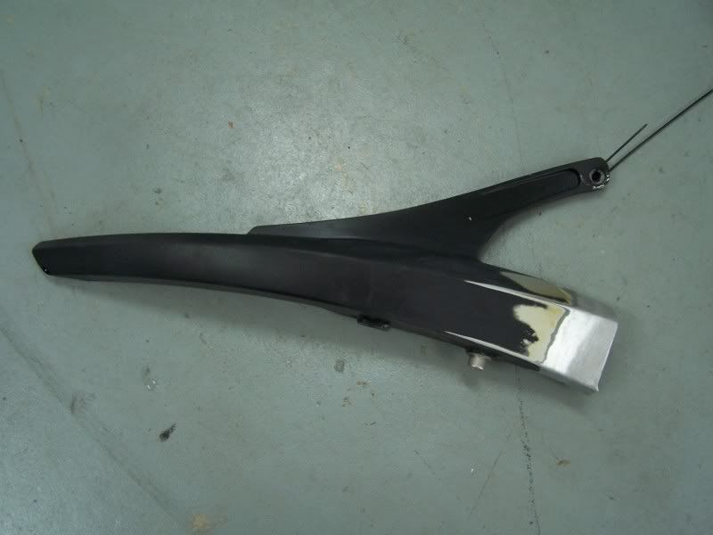 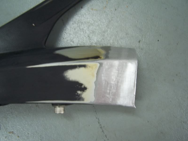 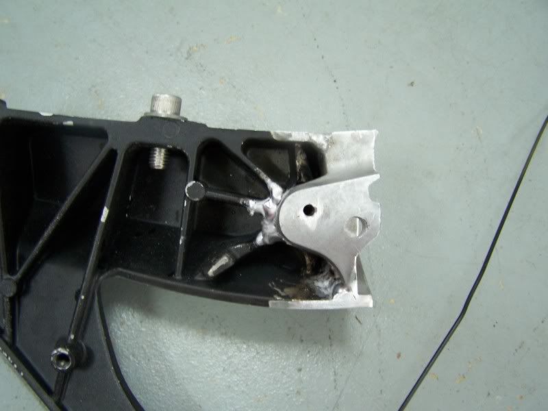 | ||
Glitch |
Nice work! | ||
Ironhead1977 |
Eric Your bike is looking good.Is that the same one you have been working on or a new one? | ||
Ericz |
It's the same one! I keep thinking of new things to do! | ||
1_mike |
Eric - On your head porting. What results ? Did you have them flow tested ? Why did you not remove or recontour the big hump in the bottom of the intake floor ? I'd like to - 1. Remove and or recontour the hump in the intake floor... or 2. Weld in the rest of the hump to the gasket surface AND build up a matching hump into the manifolds floor. I port car heads and have for quite some time. I know for fact, that removing a smaller hump that that in the Buell head can be worth quite a few CFM. BUT, if the port works better with it, I can't see how the intake manifold was ever tested actually on the head for "overall" flow. Possibly a little work as in #2 is in order for better flow. ANY port can be made better...even Buell designed ports. Mike | ||
Ericz |
Mike, I didn't want to change the overall shape of the port as this is my first time porting this type of cylinder head. I just removed all of the inconsistencies in the stock port and improved the blending between the port and the valve seat. I don't have any quantitative results of the port work yet, and any power gain on the dyno will be a result of several changes to the motor, but as I tune, I should be able to get a pretty good idea what the port work did when I compare power at the same boost levels I ran before. Since I am dropping the compression ratio to 9.6:1, the power at the previous boost levels will also reflect the drop in static compression. As far as the floor of the intake port, I have the understanding that the short side radius of the intake port should be as large as possible to maintain a more consistent velocity of the charge air. If the cross-section of the port is made more round, then the air traveling along the floor of the port has a much shorter distance to travel than along the ceiling. This creates more turbulence at the back of the valve and results in a less efficient cylinder fill. That is why most side-draft ports have more of a D-shape to the port. What are your thoughts? | ||
Ducbsa |
Cycle magazine (I think) had a feature on this maybe in the '80's on a SR500. They came up with a D shaped cross section. | ||
Xoptimizedrsx |
I added material to mine and blended it. Once ran for a while I took them off to see a pattern in coloration over time. then adjusted to that a little more. I still have D shaped intakes and slick exhaust. I wanted to do more but I was not sure if I could leaving that much stem naked in the port and shortening the guide as well. so for the final results i just turned the ends of the guide a little smaller O.D.. I did find the smoothing the exhaust side port and matching the seats on that side only is a massive change to get air out and help intake charge with the overlap. yada yada yada... seems less is more. If its black and crusty or just black/golden brown in color on that spot in the intake and or exhaust. thats your slow air location. add material there to fill the void and then blend. doing it this way takes a few times to get it better. but you know in the end your flow is even in the port. Just remember if it cant get out no work on getting it in will help. all sharp ridges must go... all intake stock have a seam line that needs blended out as well. and toss those buell header seals. get the early style flat ones they crush flat and not over into the ports. (the sporty 1200 square ones) thats all I have on this one cause I don't know any more... you can get fancy and send the heads out but a lot of places machine them bigger only and they have terrible slow spots. bigger aint always better... | ||
1_mike |
Mike - Thanks for your info and the PM. Mike and Eric - Agreed on the short turn. But for a different reason. The "flat" floor does flow better than a round floor as it goes around the short turn. This is fact. The round floor of the manifold creates terrible turbulence as the fuel/air hits the hump in the port floor. BUT...why is the bottom of the intake manifold round..and not matching the cylinder head? This manifold doesn't work with other Harley engines...! There should be a flat in the manifold floor, slowly blending into the flat of the port and "eliminating" the hump...not by removing it, but by blending smoothly from the manifold...all the way to the hump in the head. This would require some welding in the port, then remachining the gasket surface flat, along with a "ramp" in the bottom of the manifold. OR.....add some weld metal to the manifold to make it flat...then weld a "tongue" that would stick out into the head and blend with the now proper flat floor... Hmmm...time to buy another manifold... Mike | ||
Ericz |
Here are the tail pieces put together. I ended up painting and sanding several times to get the transition smooth. Black shows up every little bump and grind mark. 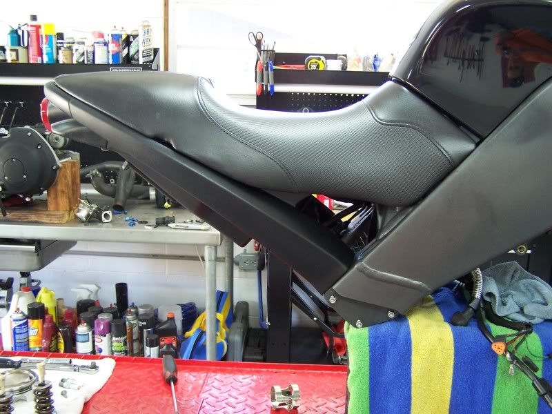 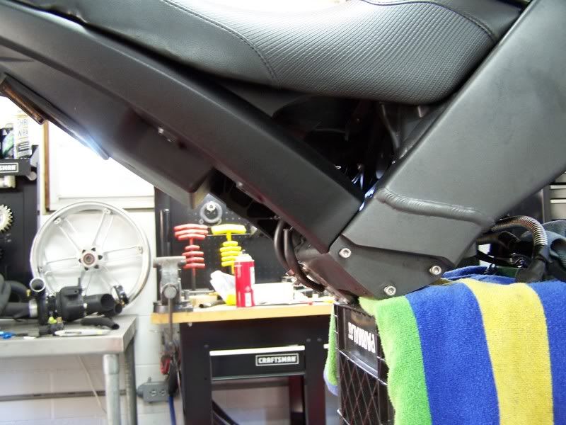 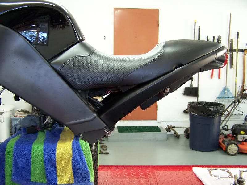 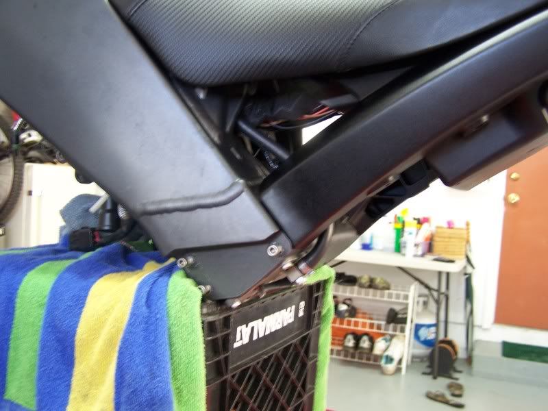 | ||
Glitch |
Extra nice! |