| Author | Message | ||
Bcool83 |
I tried searching, but couldn't find any topics on making our turn signals into running lights. I seem to remember, on another forum somewhere, seeing a relatively easy How-To on making that bike's turn signals into running lights (on all the time, but blinking when turning obviously) for a little more visibility on the road. Am I just retarded, and there is actually a thread or two on here somewhere? If not, anyone know how to do it? | ||
Bcool83 |
Wow somebody JUST posted this two days ago...nevermind! http://www.badweatherbikers.com/buell/messages/327 77/420535.html?1228931010 | ||
Sslowmo |
American sport bike has a fix for that. Seems to be plug and play. www.americansportbike.com/shoponline/ccp0-prodshow /16052.htmlortbike.com} | ||
Ulendo |
easy solution - add 2 relays, one for each side. turn signals off, run a switched 12v power ( NOT the OE turn signal feed) through the normally closed position of each relay to each side. left or right turn, use the OE signal wire to trigger the relay , and DISCONNECT the normally closed connection. it's actually blinking to 'off' but has the same visual effect as the stock arrangement, while leaving all 4 blinkers on as markers the rest of the time. for 2 lights each, even the smallest relays are sufficient, so space isnt really an issue. | ||
Bcool83 |
I was hoping for something like that Ulendo. I can't really picture it right now, but over the holidays maybe I'll try to tackle it. Can anyone see any problems with that? Are the bulbs likely to overheat and/or melt the housings if they're on all the time? | ||
Nik |
I've been running relays for ~6 months and I haven't had any problems. | ||
Midknyte |
Would this be correct? 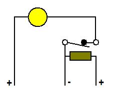 | ||
Nillaice |
i like Midknyte's how-to post a little bit ago, and makes the most sense in my head. it seems simplest to me.  | ||
Ulendo |
not quite - relays have at least 4 terminals that act as 2 pairs. ( 5 for most 'automotive style relays - 1 pair, and three that act as an 'A or B' circuit) the bulbs are already grounded one side, rather than wired, so you supply +12v constant to light them, and 'cut' the supply to make them flash. the OE signal ONLY operates the solenoid, and the other terminal of the control circuit then goes direct to ground. I'll try and draw you up a JPG. | ||
Ulendo |
okay, nice little JPEG with notes for you. Hopefully it'll get the idea across. if you need more help, just ask: I dont have a relay here at home, but I can give you the correct terminal numbers for use with a standard 5 pin relay if needed. 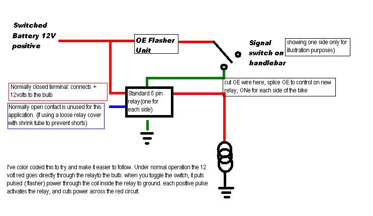 | ||
Bcool83 |
Thanks Ulendo! I just need to find a wiring diagram on here (or look it up on the CD once home) and I should be good to go! I'm sure I'll be able to figure out the terminal #s on the relays...(if not, I'll be back!) (Message edited by bcool83 on December 23, 2008) | ||
Sokota |
Where do you get these relays , Radio Shack or auto parts store ? I stopped by Radio Shack and looked at some that had "pins" for wiring ,or are there some with spade blades ? Great idea, any feedback on these in the dark questions appreciated. | ||
Bcool83 |
Sokota, I'd advise to get them from an auto parts store. I've never seen anything but spade-type relays at AutoZone, etc. Can't go wrong with those. | ||
Andymnelson |
for those that question relays, they are a very simple device. typically, they are just 2 terminals that when powered up (12v+ on one, ground on the other), they connect or disconnect 2 other terminals on the relay. they allow you to use a switch that can only handle low current to switch something draws a higher amount of current, or (as in this case) to isolate different sources in the path. typical auto relays have 5 terminals: 85 and 86- the �switch�- when 12v+ is applied to one, and ground to the other, the relay changes from connecting 30 and 87 to connecting 30 and 87a 87- normally closed contact. when relay is at rest (either no ground or no power at 85/86), then 30 is connected to this terminal. when relay is energized, 30 is broken from this terminal. 87a- normally open contact. when relay is at rest (either no ground or no power at 85/86), then 30 is not connected to this terminal. when relay is energized, 30 is connected to this terminal. 30- the power source for 87 and 87a this diagram may help the current scenario:  as you can see, the 12v+ ign switched source is normally connected to the bulb. when the turn signal flashes, the relay interrupts the path, making the bulb turn off momentarily- giving you (bright) running light and turn signal functionality with 1 single filament bulb. neat way of doing it, but isn't it illegal to have yellow rear facing lights? i thought all constantly lit rear facing lights had to be red? | ||
Metalstorm |
Eastern Beaver Company has really high quality relays. For running lights I would think the 20A mini relay would be a good choice. I wish I had pics of my S. I have two of those mini relays attached underneath my speedo console behind the fly screen that powers my headlights (they now get their juice direct from battery via the mini relays allowing them to burn brighter and eliminating all wattage from flowing through the little headlight switch). They'd work great fdor the running light mod since they'd fit inside that small space. I reckon I can go out there and take a pic so you can see what I'm talking about. (Message edited by metalstorm on December 23, 2008) | ||
Metalstorm |
Upper right, directly under the speedo.  I made a little bracket out of some thin metal to bolt the two relays together then mounted it onto the speedo console stud using the existing nut.  | ||
Midknyte |
Eastern Beaver Company has really high quality relays. And the Southern Beaver Company put out some really nice shunts. could not resist | ||
Metalstorm |
 | ||
Nik |
Where do you get these relays , Radio Shack or auto parts store ? I stopped by Radio Shack and looked at some that had "pins" for wiring ,or are there some with spade blades ? Great idea, any feedback on these in the dark questions appreciated. I used 4 of these: http://www.radioshack.com/product/index.jsp?produc tId=2062482 Soldered wires directly to the pins and crimped on bullet connectors to interface with the stock harness. Each signal is 10watts. 10W/12V = ~.83 amps. Those small radio shack relays are rated at 10 amps so they do just fine. (Message edited by nik on December 23, 2008) | ||
Metalstorm |
Oh crud, In a most horrible coffee deficit I got confused and forgot this was about blinker relays, not switched relays. Disregard my post. I'm going to step out and get me a really large and much needed cup of java. On Edit: Thankfully I'm too tired to feel embarrassed  (Message edited by metalstorm on December 23, 2008) | ||
Midknyte |
Adding an extra wire for running lights was nuthin. Finding d@mn signals that look good and don't burn up is the trick. | ||
Bcool83 |
So my (electronic) copy of the service manual has the damn wiring diagram WAY too tiny to read... So I have no idea what colors the wire are supposed to be. So I think the O/W wire going into the flasher relay (the only one I can find so far is the one up front?) is the 12v from the fuse... Then there's a brown wire going out, I presume to the switch. But I don't want to splice into that brown wire, right? I want to get into one right near the turn signal itself (where, I assume, I'd want the brown wire also... it seems the front turn signals both have one brown and one blue wire) and splice into that...?? Otherwise I don't know where to find the wire coming out of the switch... Then, I'll need to do the same thing on the other "side"...meaning I tap into the O/W wire at the same spot, and then just tap into the brown wire near the other turn signal...but I can do all of this at the front of the bike? There's not another flasher relay somewhere? Hopefully this blabbering makes sense... | ||
Sleez |
check your local regs as well, most states don't allow amber running lights in the rear. | ||
Bcool83 |
Not worried about it, but thanks! | ||
Bcool83 |
bump | ||
Bcool83 |
Nobody knows the wire colors? Midknyte, Nik, Andymnelson, Ulendo...?? | ||
Nik |
I think you're making it way harder than it has to be. There's no 'splicing' or modifying of the stock harness in any way. The turn signals each have two wires; on the signals themselves one is black the other is blue, on the bike one is black the other is something else. Black still goes to black. The relays I used go between the colored wires. You don't have to go to any higher level in the harness than that. | ||
Bcool83 |
There is splicing, or else I'm not going to have the relays connected to anything. "Splice," by its definition, means joining one thing and another... In any case, if you just put a relay "between the colored wires," can you elaborate more please? I don't understand how that ties into what Ulendo was suggesting. | ||
Nik |
On his drawing the green wire (on the bike is either brown or purple depending on side) would normally go directly to the signal, and connect to the signals blue wire. | ||
Ulendo |
You have to be far enough 'up' the circuit that both the front, and rear lights are effected. in original form theres only 1 power wire, already run through the blinker, feeding into the switch. I added the relays to the circuit where the wiring harness comes out of the handle bars/goes around the steering head assembly, and the relays are mounted behind the flyscreen. ( ** please note, I already have a 12 volt switched power supply there that provides current for my driving lights, so the second 1/2 of the circuit was relatively easy for me) | ||
Nik |
or you can just use four relays... | ||
Ulendo |
Dug out my '06 service manual LH turn signal wiring is V(iolet) RH turn signal wiring is BN(brown) looks like you should be able to tap the O(range)wire from the LH switch wiring harness for a switched 12volt source. ( thats the 10 amp brake/horn/muffler circuit, wired into the LH switch assembly for powering the horn - use a T tap, so the horn still works) | ||
Bcool83 |
I'm so confused...and I have no idea why. I'm just going to start playing with stuff and hope that one of the configurations works out...and then take pictures with a more detailed write-up after (planned). |