| Author | Message | ||
Rodrob |
Timebandit, byte 105 is not worthless. The sidestand A/D it used for a quickshifter input. | ||
Zac4mac |
Got to see some FLIR images of my 08 1125R while doing dyno runs. Unfortunately, I didn't get any copies or temps... Looking at the ignition cover, at temp and under load, the whole cover showed much the same color. Puck showed a little cooler, not much. I was hoping for some internal details to show but none did. More of a "blob" than the pix we saw of the Aprilia with FLIR. Z | ||
Timebandit |
you're misguided if you think I'm new at this. | ||
Timebandit |
Rob - thanks for the info! I guess I should have said that it's just worthless for what I'm trying to accomplish. Zack - were you capturing the FLIR images while the bike was running on the dyno? I'm thinking that if that was the case, the vibrations could have caused decreased resolution / blurring of the image that it sounds like you might be describing. Were you able to obtain any images while the motor was hot but shut off? I think those Aprilia photos were taken with a hot bike shut off. | ||
Zac4mac |
Bob - no. Camera was run by a Schaeffer Oil rep and he wasn't happy that his oil didn't run cooler and make more power than other oils... He was supposed to e-mail me some images from the FLIR but never did. | ||
Hildstrom |
Here are the results from a long test ride this weekend:   I stopped for 10 minutes of idling on top of a concrete parking garage, which explains the drop in ambient air temperatures during that time. Ambient temperatures were low-mid 90's and higher on the black stuff. | ||
Dannybuell |
Correct/Help me understand; Graph #1 It looks like the electrical system is good as long as the bike is moving. Graph #2 What does the fan (pink) dip at 73 minutes mean? Is the spike at 94 minutes the second fan coming on? | ||
Hildstrom |
Yes, stator and regulator temperatures look fine to me. The fan duty cycle dip at 73 minutes means less fan was needed because of battery voltage or temperature. Look at air temperature in the first graph and speed in the second graph. This was when I stopped on the concrete parking garage and it was cooler. I'm not sure why the fan duty cycle ever goes above 100, but I imagine it is a value calculated by the ECM. | ||
Hildstrom |
Timebandit posted some good analysis of my last set of data in another thread. I agree with most of his analysis in that post except part of number 6. Stator temperature continued to climb while coolant temperature was decreasing because the fans were still running full blast and rpm/speed were low. Regardless of rotor type, stator temperature cannot change instantaneously and it will lag the other measurements. I agree, as I have before, that the oil-cooling rotor can remove more heat faster than my air-cooling rotor. However, we do not have enough data to say the air-cooling rotor is not working. I need to capture the idle plateau temperature to know if my setup can survive conditions worse than I have tested so far. We would need a similar measurement with the stock rotor to quantify its relative performance. I went on an 80 mile ride today, from San Antonio to Bandera and back. It was beautiful riding through the hill country. When I got home, I put the bike on the rear stand and let it idle. My intent was to start idling with everything already heated up pretty good and to let it idle long enough to capture the plateau. I idled for 40 minutes, coolant temperature stabilized at 223F, and battery voltage hovered around 12.5. Then I switched off my rear fuel injector. I idled for 20 minutes, coolant temperature dropped to 190F, and battery voltage hovered around 12.7. Unfortunately, after all this, my data looked like crap. Some combination of vibration and heat resulted in an intermittent short/open to the max6675 chip or its connection to the thermocouple. It's also possible that the chip was heated past it's compensation range. So, I need to perform this experiment again. I removed the Arduino and connected a different max6675 breakout board without the ProtoShield and other sensors. When I have time, I'll go on another pre-heat ride, return home, and connect my laptop/Arduino to the stator thermocouple and try to capture the idle plateau. | ||
Timebandit |
Greg, you make valid points. I'm bumming when I hear about the instrumentation problems you're having. It really stinks that you've gone through all the effort to collect data, and that some technical problem scuttled all of your efforts. I hope that the thermocouple is OK. It wouldn't be so bad if it was just an instrumentation error or a loose wire, but it would really be frustrating if the embedded sensor went bad on you. Good luck. | ||
Nightsky |
I wouldn't expect rotor air holes to provide measurable cooling. There is no air exchange in the closed crankcase. It's the same trapped hot air. Oil works because it gets circulated through the cooler and has much higher specific heat. | ||
Mako |
letting a little oil mist onto stator could help I think if the ports were large enough or try to turn the ports into a fan of sorts? | ||
Timebandit |
Misting works pretty well for cooling you off when it's hot outside. A little water mist can really help to cool a person off when it's 105*F outside. There are a number of reasons that water misting works for people who live in the desert: 1. When the water mist evaporates, it releases a lot of energy. The boiling point for water is low, and the heat of vaporization is for water is high because it's a highly polar molecule. 2. The amount of temperature reduction from 105*F ambient to 95*F on the skin isn't very much -- only on the order of 10*F. 3. Very little water mass is needed to achieve a 10*F temp reduction, because the temperature drop is low, and the heat of vaporization is high. Now look at a stator/rotor: 1. Synthetic oil has a boiling point of ~400*F. 2. The latent heat of vaporization for oil is lower than that of water because it is less polar. 3. The amount of temperature reduction required by the stator is higher by an order of magnitude. We know that these stators are operating at near ~300*F with a series vreg, and may be a lot higher with a shunt vreg. We want to achieve a reduction to the oil temp of 200*F. That's a minimum drop of 100*F. Maybe more. 4. Lots of oil mass is going to be required to drop the stator temp from 300*F to 200*F; we're looking for temperature reduction of at least 100*F (maybe more), the latent heat of vaporization of oil is low, and the specific heat of mist is low compared to liquid oil. That means you need LOTS of oil to carry away the heat. It's really hard to imagine that misting could provide a meaningful result. To remove that much heat, you need to pour cooled oil on the rotor. Isothermal mist in a closed box can't exchange heat. We discussed this stuff in another post in another thread. There are several methods in which heat transfer can occur. The formula is very complex, but it's easy enough to understand if you ignore the complex terms in the heat equation, and focus on the size of the coefficients that precede each term in the equation. The terms that have small coefficients in front of them can only play small roles in heat transfer, while the terms that have large coefficients in front of them play large roles in heat transfer. Simple math dictates that to get the most out of your effort, you want to utilize the methods of heat transfer that have large coefficients in the heat formula. | ||
Hildstrom |
With the air-cooling rotor, the air/oil mist is in contact with the stator, engine internals (oil-cooled), and the cases (water-cooled). That same trapped hot air is kept at some temperature by the oil cooler and the radiators. As long as that trapped hot air is cooler than an overheating stator, circulating it is beneficial. Directly sprayed oil is probably better, but my idle plateau test today shows that my air-cooling rotor is sufficient under these worst-case conditions. Ambient air temperature was 100F. I went for a 1-hour ride around town and then pulled into the garage. I put the bike on a rear stand and put a 24" fan behind the rear tire blowing out of the garage. Both doors were open. Ambient air temperature rose from 100F to 104F during the test. I connected my Arduino and MAX6675 board to my laptop and to the stator thermocouple leads. I idled for 40 minutes and observed the plateau of 163C or 325F; maximum coolant temperature was 225F. At minute 47, I disconnected the rear fuel injector and later observed a higher peak of 167C or 333F. At minute 50, coolant temperature was 211F. At minute 66 coolant temperature was 194F. I think stator temperature rose 4 degrees when the rear injector was disconnected because of the slight drop in idle speed and the rough running on one cylinder with the high fan current draw. It took a while, 20+ minutes, but coolant temperature dropped enough so the ECM could reduce fan duty cycle and the combination eventually reduced stator temperature. At minute 71, stator temperature was 159C or 318F and I turned off the engine. I am pleased with these results. My stator should survive this kind of torture indefinitely. Even a stator wound with 200C insulated wire instead of 240C insulated wire should survive this torture. These numbers lead me to believe that the air-cooling rotor is an improvement over stock, but I do not know by how much. I am also pleased with the rear fuel injector disconnect modification because it works. If I had started the idle test with the rear injector disconnected, like shifting into neutral with the mod at a light, coolant and stator temperatures would never have climbed to the plateau levels I observed. The results from logdata07.txt are plotted here:  Under the conditions that I normally operate the bike, including up to 10 minutes of idling, I have not observed stator temperature above 300F. | ||
Hildstrom |
Also, the fuel started boiling at some point during the test. Gasoline vapor was coming out of the vent tube with a surprising amount of force. | ||
Timebandit |
Interesting set of data, Greg. I've re-plotted it to separate the different test conditions as you've described them. I think doing that makes it easier to see what's really happening: 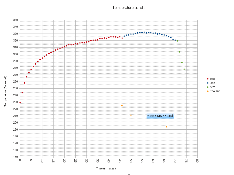 Could you post your complete set of acquired data? It would be interesting to see other data that was collected concurrently; RPM and CT would be particularly interesting to look at. If you could supply the complete set of raw data, I'd be interested in looking at it. | ||
Hildstrom |
Thanks, that graph is easier to read. I logged stator thermocouple temperature alone because I removed the Arduino from the ProtoShield, which was giving me frequent drop-outs in stator thermocouple temperature. RPM is similar to my previous 10-minute idle from 0-46. Then RPM is a little lower, noisy, and not smooth from 47-70. RPM is zero from 71+. CT was between 223F and 225F from 26-46. That's as far as my notes can take us without having everything logged. (Message edited by hildstrom on June 26, 2012) | ||
Timebandit |
It's disappointing to hear that you're having problems with the logging hardware. I hope that you can get it all straightened out. It would be great to have other data, like RPM and CT for comparison. I think that the data that we have here provides some very useful insights into how the stator behaves at idle. But more importantly, it tells us a lot about heat accumulation in the bike. From a practical standpoint, the experiment was designed with real-world application in mind -- specifically, it asks the question: "If you're idling and the bike is getting hot, does shutting off the rear cylinder help you?" The obvious implication is that shutting off one cylinder helps A LOT to reduce CT, but not so much to reduce Ts. Without the actual RPM data, it's hard to say exactly what the effects of RPM may be. The blue curve's continuing ascent with the rear cylinder shut off suggests a number of things: A) It could be that 2-cylinder Ts hadn't yet plateaued, as it looks like Ts continued to rise for another 10 minutes; B) It could be that there is a 10-minute phase lag in the time that it takes stator winding and core heat to migrate through the epoxy to the sensor. The epoxy does have a fairly low heat transfer number; C) It could be that the difference in one vs. two cylinders has a large impact on CT but that it doesn't have any major impact on Ts. It's entirely possible that Ts is dependent upon RPM, airflow, and duration. We already know that RPM plays a large role in stator heat generation. We don't have enough hard/fast data to give an absolute answer about duration. Without more data, it's not really possible to draw solid conclusions on any of these ideas. A more complete set of data is needed, optimally something that can trace Ts and RPM concurrently. There's another point I might add -- and this amounts to total nitpicking on my part. The experiment that you performed was optimized to provide practical answers to the question of "What happens when I shut off one cylinder at idle?" Another experimental design might be optimized to provide more clear/unambiguous answers about what the difference is on heat accumulation with 1 vs 2 cylinders running. It would be interesting to perform a 1-cylinder idle test, and compare the rate of heat accumulation vs the 2 cylinder idle test. Doing that could help to assess the difference in heat accumulation that is attributable to combustion vs. that which is attributable to internal stator heat generation. Of course, the best way to get that answer would be to spin the stator with 0 cylinders running, though that's a harder setup to obtain. What frustrates me is the blue section of the curve. It's a smeared mess that's comprised of two different opposing forces that are acting against one another at the same time -- one cylinder is generating heat while one cylinder is cooling. The blue area is actually a combination of the descent area for the rear cylinder (green type curve)r, and an ongoing ascent heat cycle (red curve) for the front cylinder. It's a mess that's very hard to interpret. Perhaps the most interesting section of the graph is the part where you stopped the experiment. Although I wish you'd let the red area go on a lot longer, I really wish you'd logged a lot more data in the green section of the curve. The thermal recovery phase tells us lots of things that we really need to know. | ||
Timebandit |
error note: sentence toward the end of the above post should have read like this: "Of course, the best way to get that answer would be to spin the rotor with 0 cylinders running, though that's a harder setup to obtain." | ||
Hildstrom |
Timebandit: Good observations. A) 2-cylinder operation plateaued. It seemed pretty clear to me as I watched the numbers on the laptop screen. Samples 40-46 were stable and not increasing. If I decide to do it again with a reworked logger, I'll let it plateau longer. B) My thermocouple is in direct contact with the windings between the bases of two poles. I wedged it in there and then covered it with a lot of epoxy. C) Agreed. It would be nice to have the entire heat up and cool down logged along with all of the other sensors for both 2-cylinder operation and 1-cylinder operation. I'm in the process of moving over the next couple of weeks, so this will have to do for now. Thanks for the feedback. | ||
Timebandit |
Part C should have also said "and not combustion", but I think you know what I meant by that. Moving? Aargh. Better you than me. I'm putting it off for as long as I can. I'm not sure that the red section of the curve has plateaued. In fact, we know it hasn't. Using the data that you have for the two cylinder section, regression yields several solutions with really nice fits and high R-squared. I've posted one below. Of course, this would be impossible to see on a PC screen in real time as you're collecting data: 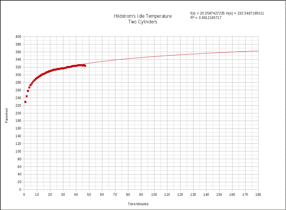 I think that this tells us that Ts is going to continually increase toward an asymptotic value. At a billion minutes (!) that could be as high as 925*F and still be increasing. Not that THAT really matters to us. A more practical limitation is the amount of fuel in the tank or how long we're willing to idle. If we set the limit of our period of interest to 3 hours, the extrapolated plot would look like the one above. I think that the bottom line is that to know how hot the stator gets in real-world, long-term usage, the best way to collect that data would be to ride the bike at highway speeds until the amount of fuel in the tank forces you to stop to refuel. That would provide a very valuable, practical answer for how hot the stator gets on the longest possible ride. What's far more interesting to me is the recovery period. Your data set shows that the recovery period for the bike isn't all that long. It would be very interesting to collect a set of long-term recovery data as well. Here's what I was able to put together from your data. The problem is that the number of data points is too small to be trusted, but it suggests that shutting off the engine for 10-15 minutes (such as a fuel stop) results in significant stator cooling: 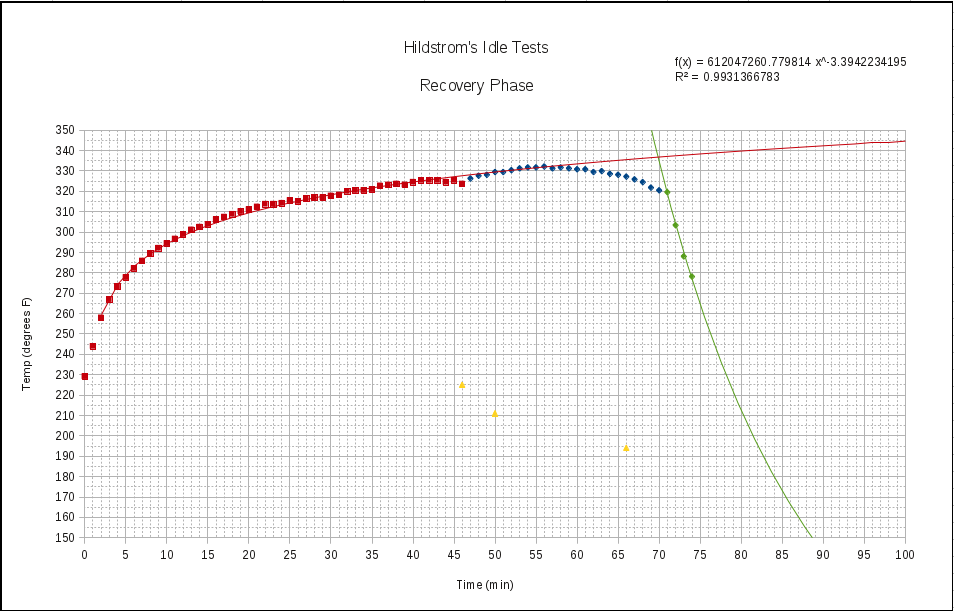 The obvious conclusion is that instead of taking a 3-hour ride, your stator will be better off if you cut the ride in half, and stop for 10-15 minutes to let the stator cool down. It'd really be interesting to see what a plot looks like when you ride until the tank is empty, refuel, and ride again. | ||
Sparky |
Would it be a good idea to disconnect the stator to find out where Ts goes with a hot running engine in the hopes of determining how much heat comes from combustion? I'm thinking that an open-circuited delta wired stator won't produce current and thus heat or will it? | ||
Hildstrom |
Time bandit: I saw 41 163.00 42 163.00 43 163.00 44 162.50 45 163.00 46 162.00 That looked like stator temperature had stopped increasing and reached a plateau to me, but I should have let it run longer. Your regressions are pretty cool. The first regression has the worst fit on the last few samples before I cut the rear injector, so I'm not sure I would conclude that it would keep increasing until you run out of fuel. We need more data. Sparky: That's not a bad idea at all. The disconnected stator will not produce any current or heat. Here's what I'm thinking for rotor testing next time: * fix logger * sample faster (10 samples/minute) * start cold to capture the entire heat-up curve * idle for 2 or 3 hours * turn off bike * continue recording overnight to capture the entire cool-down curve If we feel there is value, I can repeat the test with the entire stator disconnected. I can also repeat the test with the rear injector disconnected to quantify the relative performance of that mod with the air-cooling rotor. I'm definitely going to rig up a condenser for all of the gasoline vapor next time. On my way back from getting the mail, it smelled like gasoline across the street two houses down, which was inconsiderate of me. I wonder how much I boiled off. | ||
Timebandit |
although the plots don't seem to show it, the regression curve for the red plot does go through all of the red sample points, even those on the far left. the appearance that it doesn't follow all of the data set in the above charts might be an artifact of scaling in the plots. the "worst fit on the last samples" that you're concerned about falls within the range of measurement error on your instrumentation: you're fussing about whether the real temperature of ~320*F is within 2*F of it's measured value on a system that you knew to be malfunctioning. statistically, there are going to be samples that fall above and below the curve due to error occurrence in the system. distribution about the line is to be expected in real world data. your data is no exception. what is most striking in your data is that the residual error in the system appears to be so small. the Coefficient of Determination (R-squared), which is a measure of goodness of fit is astronomically high. http://en.wikipedia.org/wiki/Goodness_of_fit In a system that is positively correlated, this number can range from Zero (no correlation) to One (perfect correlation). All of your solutions are greater than 0.99/1.00. Those are some of the best fitting data that I've seen, regardless of those last few dots that you think nullify the sample. statisticians understand that they they don't. In the chart below, which uses all of the data out to 50 minutes, the solution is even better: 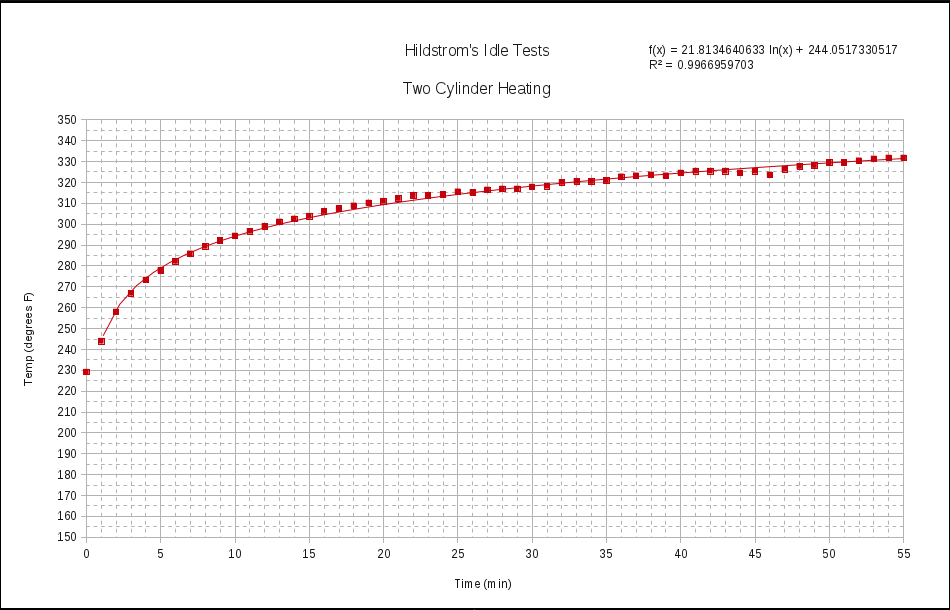 What's important to note about this analysis is that in science and engineering, fits of this quality are not commonly achieved. the deviation that you're concerned about in the last couple of points in the two-cylinder phase is statistically insignificant. The goodness of fit criterion of 0.9967/1.0000 tells us that there is an exceptionally high ability for the mathematical model to accurately predict temperature. if the shoe fits, wear it. (Message edited by timebandit on June 27, 2012) | ||
Nightsky |
There are two components to stator temperature: 1) Heat from combustion 2) Stator electrical heat Note stator temp climbs another seven degrees, even after one cylinder is disabled. This tells us temperature from electrical loss is still rising, because combustion temp can only be dropping. The combustion contribution to stator temperature will plateau early, while the electrical portion will continue to climb. Fuel boils off, and that phase transition from liquid to gas will help hold overall engine temp constant as long as enough fuel remains. The stator has no oil or coolant, with limited thermal contact to the outside world. The stator with its internal electrical heat source will stabilize at a much higher temp than the engine. (Message edited by Nightsky on June 27, 2012) | ||
Timebandit |
i had previously pointed out the time lag between the time of the shutoff event and the time of peak sensor readings. it's precisely why my last chart uses all of the data going out to 55 minutes, even though the rear cylinder was shut down at 46. | ||
Baf |
Just rewound my stator. Fingers are sore now, but the epoxy is on the windings curing. In 24 hours, I'll do the post-cure on the epoxy, then reassemble everything. | ||
Hildstrom |
Baf: Very cool. Be very careful installing the stator in the case. Make sure you don't pinch any wires or solder joints like I did. Check for shorts to ground at every step. Check idle and 3k AC voltage before you hook it up to your regulator. I hope things go smooth for you. | ||
Baf |
Will do. I managed to get the fabric covers off that were over the connections with minimal destruction, so I'm going to keep them in place to help protect a bit more. I've been busy the past couple days, but I'm hoping to get it buttoned up tonight. I also bought a CE-605 SB to install too. A few of the poles on the stator came out messier than I like, but hopefully that doesn't affect performance. I have another empty stator core here that I'm going to wind, and pay much more attention to keeping the windings neat, just so I have one ready to go if this one craps out. I spent around $180 shipped on the wire, and $110 shipped on the duralco 4461 epoxy, and I have plenty here to wind at least 4 more (8 if I use less epoxy - this epoxy was so thin that a lot of it ran out, so if I'm not as wasteful, I can probably use half as much). For less than the cost of a new OEM stator, I bought enough materials for multiple re-winds. I used roughly $50 in materials doing this wind. I mostly followed your writeup, so thanks for that Hildstrom. I did wrap the laminations with a few layers of teflon tape to provide a little more lamination/protection. Teflon tape should be good to 300+ Celsius. (Message edited by baf on July 03, 2012) | ||
Hildstrom |
Teflon tape? Interesting. Didn't your laminations already have a black plastic coating on them? |