| Author | Message | ||
Timebandit |
Ad hominem. | ||
Timebandit |
> heat seems to be the culprit... Heat is the worst enemy of any electronic device. One reason that the Buell vregs fail because they're trapped in a lousy position near that hot motor. People replace them with aftermarket products, and move the aftermarket products to a cooler location, and then claim that the aftermarket products are better. Why don't these people just move their Buell regulator to a cooler location in the first place? | ||
Stimbrell |
Just a completely wild, totally out there thought, but perhaps people who have purchased a new bike that for some is still under warranty, do not really expect to have to move the regulator to a cooler location to stop it failing. How stupid of us owners! expecting the bike to work as we purchased it from the showroom. | ||
Posplayr |
I did a quick set of calculation based on some more of the new information. Timebandit has a great concern about the Faraday effect (we are impressed) and the potential incompatibility between the Compufire and the Buell stator. The "Faraday effect" simply means that the open loop voltage of the stator is proportional to the RPM. It does not mean that that current,power or voltage is proportional to RPM under normally connected operation. Timebandit go see if you can figure that one out??? The only reason this would be a concern is when the SERIES R/R opens the stator circuit (as opposed to Shorting the stators as the SHUNT R/R does) the voltage goes to the no load values. The GS Suzuki's stock stator are 80 VAC at 5000 RPM No load tests (stator leads disconnected). The Buell is about 51 VAC at 4000 RPM (same test) The GS redline is 10,000 (I go there regularly) The Buell is 13,000 Comparing the maximum voltages you have 160 VAC as compared to 167 VAC for GS and Buell respectively. In effect they are nearly identical. In addition this type of design had better have some high voltage protected MOSFETS because of the likelihood of large voltage spikes any time you try and instantaneously current the current through a winding V=L{dI/dT}. So you can pretty much rest assured that the FETS are probably good for 200 to 250 volts at least. 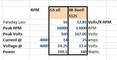 Here is a post back just shy of two years ago where I had installed an oil sprayer onto my stator PRIOR to finding a suitable SERIES R/R. I found and installed the COMPUFIRE after this photo was taken. After riding to Kris V's last weekend to see Bill start his 1229, I experienced much cooler temperatures (210 and below) and my stator is no worse than what it was before. Apparently the sprayer is keeping it cooler. I'm using 4AN line with 1/8" NPT fittings. There is a restrictor which is about 0.090" (approx). Bottom line this seems to be very effective at keep the stator cool. If you are not going to get a SERIES R/R, then I would certainly recommend this. Just based on the pressure drop with the Hi Po gears I would also do it. You can see the sprayer; the end has been ground off a little to insure it clears the rotor. http://www.thegsresources.com/_forum/showpost.php?p=1228981&postcount=38 One last thing. The Cycle Electric SERIES R/R is implemented with bipolar SCR's. It is an older design and that is why it gets so hot. The high forward voltage drop of those SCR in conduction. Most likely this is due to the simpler control scheme for turning off SCR's. The Compufire on the other hand is MOSFET based and it does not have nearly the same voltage drop as the SCRs. That is why it is capable of providing the same 25 amps of current without getting hot like the CE series. Based on third had conversations, someone reported that Compufire said the CF SERIES R/R will actually handle 60 amps.Further evidence it is a newer, more reliable SERIES R/R design. Effectively the Compufire MOSFET SERIES R/R is 90%-95% efficient like any good FET based power design. The SHUNT and SERIES R/R generally switch when the AC current is near a cross over (i.e. near zero) which means they are synchronous devices. In contrast a "switcher" DC to DC device would require a large energy absorbing device on the output and you are just not going to see that and it would be chopping the inductive source during high current portions of the AC cycle. This would be VERY VERY noisy to say the least. A switching DC to DC converter is NOT appropriate for this application and you will never see one. The COMPUFIRE or equivalent is as good as it is going to get. the only only FET based SERIES that I know of is this one (maybe I can not confirm it) http://www.thegsresources.com/_forum/showthread.php?t=188998 A German made SERIES R/R that has been around for about 30 years http://www.silent-hektik.com/Duc_R_Duc.htm #1 Switches in and out the high side of the battery with minimal load. "High Side Control" #2 Switches in and out the low side of the battery with minimal load. "Low Side Control" #3 Between the poles, short circuits with extreme high load. interpretation: The Compufire CF55402 or CE-605 is similar to either #1 or #2 for all intents and purposes those are all SERIES R/R's (Message edited by posplayr on June 08, 2012) | ||
Timebandit |
I think that trying to solve a problem is more productive than pissing and moaning about it. | ||
Stimbrell |
Again I say "under warranty" | ||
Timebandit |
FYI my previous post was intended to follow Stimbrell's. Instead of constantly complaining, I think it's more productive to look for a solution to the problem. I think we should give credit to everyone who's participated in the effort of looking for solutions to the problem; even though people don't always come up with the right answers, at least they're trying to solve the problem. (Message edited by timebandit on June 08, 2012) | ||
Timebandit |
I see that there are no responses to my comments about the FLIR photos not actually depicting what they were claimed to have been depicting. > "It does not mean that that current,power or voltage is proportional to RPM under normally connected operation." > "The COMPUFIRE or equivalent is as good as it is going to get." I recommend that everyone interested in the technical aspects of this discussion should download and save that PDF that PoS posted in one of his previous posts. Specifically, you want to have the PDF that contains the oscilloscope screen shots. You're going to need them for reference. (Message edited by timebandit on June 08, 2012) | ||
Nuts4mc |
my strategy was to get to a consensus on the location of the VR as a possible "root cause" to the stator failures...maybe my time is better spent building a "tail tidey" with an extension wire harness and bolt patterns to accept the (3) (OEM(Ducati), Shindengen, Compufire)different VRs. Mount them in the air stream under the seat near the tail light, rather than building a stator winder and sourcing wire and laminations! | ||
Timebandit |
As far as a "root cause" goes, I think that those people who recognized the "hotbox" problem (with the regulator mounted inside of the frame near the cylinder head) immediately recognized a large part of the problem relating to regulator reliability. BMC attempted to solve the heat transfer problem by heatsinking the vreg to the frame. It was a logical starting effort for a new design, but success was limited because the thermal mass of the frame is not that high and air cooling is not great. I think that the combination of placing it on a larger thermal mass, and in a location with higher airflow across supplemental cooling fins are definitely smart ideas. I think it's important not to underestimate the importance of direct heatsinking to a heavy thermal mass that is readily cooled. Using a large, heavy, finned thermal mass would definitely result in better cooling than just sticking the vreg in the wind. The price that you pay for that incremental gain in reliability is paid in the currency of mass. Not everyone will consider that a good tradeoff. For a commuter, yes. For a sportbike, probably. For a race bike, no way. | ||
Posplayr |
Timebandit those thermal images Are not worth debating anyone that has a series's r/r will be able to confirm that their bikes are running cooler( if they have a way to measure it). The compufire r/r will also stay cooler as it is a fet device. YMMV but on my bike there was a 30-40 degF drop in oil temperature. The whole bike runs cooler | ||
Timebandit |
Are you still claiming that the Compufire is a true series regulator? | ||
Posplayr |
The most effective way to cool your R/R is to create a thermal bond between it and the metal frame of your motorcycle. The problem is how to get a low thermal resistance path between a flat sided R/R and a ob-longed motorcycle frame member? One way that I devised was to mount the R/R in place on top of a pair of flattened pieces of copper (1" copper tubing flattened with a hammer). The heat sink mounts between the R/R and the normal mounting point. The copper extends up to a point where the copper can be bonded to the frame. To enhance the thermal bond I used thermal grease (i.e. heat sink grease to increase the contact area) to further enhance the frame to heat sink bond I used a wire mesh to get more contact area due to the mating of a round frame tube with the rounded heat sink. To confirm your installation is effective you can measure the temperature differential between the R/R case and the frame just the other side of the bond. I was able to achieve about 10-20 degF of drop. (The lower the better) That means my R/R never got more than 20 degrees more than my frame temperature. http://www.thegsresources.com/_forum/picture.php?a lbumid=1998&pictureid=10869 A FLUKE 50D is real useful for doing this. \newurlhttp://www.onlinecomponents.com/viewer.aspx?p=11344341&Resource=1 (Message edited by posplayr on June 08, 2012) (Message edited by posplayr on June 08, 2012) | ||
Timebandit |
The 1125 already has a heatsink plate that is welded to the metal frame, and the case of the regulator already forms a thermal junction to the plate using thermally conductive grease. Your proposed Suzuki mods don't bring anything to the table that the Buell 1125 doesn't already have. I think your Suzuki mods would me more interesting to people on a Suzuki forum. They certainly don't offer anything new for the 1125 application. I'm still waiting on an answer regarding whether or not you think the Compufire is truly a series regulator. Those scope shots in your PDF provide a lot of revealing information about the Compufire and how it works. As you said, there is a question of whether or not someone understands what the data is telling them. You challenged my understanding of your data. Let's go through it and see who understands and who doesn't. | ||
Nuts4mc |
Thanks guys! - I have had experience with the use of thermal grease in large Solid State AC motor drives(used to apply it to the heat sink extrusions with paint rollers!)...do you have an "idea" of the "normal" operating temp of the VR? (any brand/type...looking for a starting point)...can't open the "gif" above. | ||
Timebandit |
aw crap ... I meant to say "would BE more interesting to people on a Suzuki forum," not "ME more interesting." I couldn't get the image to open either. I haven't been measuring vreg temps on our bike, because my primary concern does not involve worrying about protecting regulators. Regulators are cheap to buy and easy to install. Stators are expensive and more of a PITA to replace. | ||
Dannybuell |
keeping your eye on the ball? | ||
Posplayr |
TB: The Compufire is a SERIES R/R they sell it that way and I confirmed it by the measurements in my post. That should be patently obvious, but I'm sure you have an issue with that no doubt... A thin metal plate is a bad heat path. Thermal resistance is: inversely proportional to cross sectional area and proportional to the length perpendicular to the cross section. So a thin metal plate is about the worst you can do. That is more likely why it is not working, If the frame is cold and the R/R is hot then the bond to the frame is not very effective. | ||
Nuts4mc |
Thnx Pos- I'll look at what Aham-Tor/Wakefield has to offer | ||
Timebandit |
Like I said before, I don't care about the marketing claims that are made when someone tries to sell widgets. What I care about is measured performance, not lip service. By looking at real data, I can see through the misrepresentations and lies. I didn't ask about Compufire's marketing claims -- I asked whether YOU think that the Compufire is a true series regulator based upon YOUR experimental data. Whether Compufire claims that their product is a true series regulator, and they sell it as such, has nothing to do with the facts of how the product functions electronically under real world testing. Your measurement data speaks for itself. What I'm asking is for you to provide your interpretation of your data, and to put your reputation as engineer on the line as being right or wrong. Again, is the Compufire a true series regulator? Yes or No. Before we dig into the discussion of the technical details, I would like for you to answer a question about what information you are trying to convey to the reader by creating the red plot (lead 3) in your charts that you refer to as "calculated power." I understand exactly what it means, but it would be helpful for those following along in this thread if you would explain exactly what information you intended to convey to the reader when calculating and plotting those red curves. It would be helpful to pin down exactly what portion of the charging system you are modelling when you draw the red curves, and also, to pin down exactly what parts of the charging system are not modelled by the red curves. I'm pinning you down so there is no wiggle room. When we have solid, clear answers about what each piece of data is supposed to represent, then we can start to talk about the data and what it really means. (Message edited by timebandit on June 08, 2012) | ||
Posplayr |
TB: The red plot is a MATH function in the scope. It is the product of the other two plots. Since one is Volts and the other is Amps it directly computes Power-Watts. I indicated a caveat in the interpretation of the math function. The Power computed is basically power delivered to the R/R by the stator. It is sometimes the power in the stator. It is getting close happy hour | ||
Timebandit |
I understand that the red trace is a product of the yellow and blue traces. What I'm most interested in hearing is your interpretation of what the area under the red curve actually represents.
This is your last chance for retraction. Is that your final answer? | ||
Dannybuell |
TB ~ It seems that you are missing an opportunity for a collaboration. | ||
Timebandit |
I'll pick my team. You pick yours. | ||
Posplayr |
go ahead bubba; take your best shot  | ||
Nightsky |
Hi Pos, The waveforms are appreciated. There's been a lot of debate on this thread about series regulation vs. shunt regulation. I don't think we'll get anywhere without agreeing what a series regulator is. What defines a series regulator and what does it do? What are the differences between a series and a shunt regulator? (Message edited by Nightsky on June 09, 2012) | ||
Dannybuell |
Badweb is a group of Buell enthusiasts sharing their passion for mc's. Timebandit ~ I read Posplayr's posts long before reading your posts. As naive as my questions may have been, Posplayr's answers were polite and succinct. Calling someone a salesman as a pejorative shows no desire to facilitate and get along, exactly what a salesman does. I can count on one hand the number of personal attacks I have seen on this site in the last two years. We can all do better. | ||
Posplayr |
SHUNT shorts the stator windings SERIES is in series between the stator and load. | ||
Nightsky |
I think everyone on the board has figured out shunt regulators. We know the shunt regulator sits across the load and shorts just enough to get 14.0V out. All regulators are between the stator and the load, so they are all "series" in a sense. How does the series regulator maintain 14.0 volts at the load? How does it work? What do I look for in your waveforms? (Message edited by Nightsky on June 09, 2012) | ||
Curve__carver |
I could definitely do without TB's attitude. |