| Author | Message | ||
Jdmagri |
Well I believe I failed my second stator, which apparently isn't so bad for 24k miles. First one went at 7k miles and then the harness "upgrade" as HD calls it, was done. While on a 4000 mile trip in 2010 I melted down the relay in the harness in Miami Fl in very hot ambient temperatures. My 09 CR is now out of warranty, however I have contacted HD customer service (414) 343-4056 and explained the situation with repetitive failures of the charging system. My respectful yet factual arguments seemed pretty well received by the customer care individuals I spoke with. They have filled out a reference # with all my information and said that if my dealer diagnoses the issue they can then submit a request for "out of warranty assistance". This request will then either be accepted or denied by HD customer care. If they deny the claim I am out the diagnoses fee, about 1 hour of shop time or $96.00. If the claim is accepted I will get a new stator for free. My ultimate question is what is the best package to make sure this never happens again. I have ridden my CR over 1000 miles in a day and can't handle any more reliability issues with the system on long trips. If I get a new stator my plan is to bring it home and tear it back apart. I'm thinking that the best package is as follows: -New 09/10 Stator -Modified rotor from EBR with oil cooling -Remove the harness "upgrade" -Install a new Voltage Regulator CE 605 sb seems to be the favorite. Have I missed anything or please feel free to give comments about the pros or cons of doing these all together. Please note that I do understand the 08 stator and rotor setup is pretty bulletproof, however I do want to run heated grips so the the output needs to be higher such as the 09/10 option. Thanks for all the help everyone, this forum is really an amazing wealth of information regarding these failures and the experiments that all of our intelligent members have preformed and shared. Keep em shiny side up, Justin | ||
Dannybuell |
Looks like you have touched all the bases. | ||
Jdmagri |
Is it defiantly EBR's recommendation to remove the HD harness upgrade? Is the control wire for the relay separately wired into the loom which goes to the ECU? It seems to me I saw an additional wire the last time I had the left pod apart. | ||
Timebandit |
Removing the harness update will not make the stator run any cooler. | ||
Jdmagri |
I agree but it will allow the system to charge at a little bit higher voltages and eliminate the issue of overheating the add in relay in the harness, correct? Is there still risk of melting wiring with the harness removed? | ||
Baf |
I'm still not convinced that the harness is necessary with the EBR rotor. Sure there is lower oil pressure at idle, but the oil jet is tiny - I can't imagine it takes very much oil at all to keep the stator wet. I started a thread on this, and Timebandit was the only one to respond. I'm still debating whether or not to do as you've outlined and swap regulators and remove harness, or leave everything stock (aside from rotor). I'll have to see what my stator looks like when I pull everything apart; the bike has just over 12k on it, with original stator, so if it looks relatively healthy, I may just leave the harness and regulator as-is. | ||
Timebandit |
"but it will allow the system to charge at a little bit higher voltages...?" yes and no. if you operate under the conditions that activate the harness, then yes -- you can get higher voltage output in the single-phasing region by removing the harness so that it never single phases. if you don't operate under the conditions that activate the harness, then no -- you won't see any difference. there isn't any reduction in voltage caused by a properly functioning harness when it is not activated. "...eliminate the issue of overheating the add in relay in the harness, correct?" the failure mode in the relays looks like it's caused by arcing, because the harness update was not designed with arc-suppression in mind. arcing will eventually carbon-foul the relay contacts and cause it to fail. as you know, carbon-fouling causes increased resistance across the junction, and high current flow causes power to be dissipated across the resistance as heat, which can melt wires. there are many easy ways to eliminate the relay problem. one would be to remove the harness so that there is no relay. one would be to revise the harness to incorporate arc suppression. another would be to periodically replace the relay during preventive maintenance. the relay is a $4 part. | ||
Timebandit |
"I'm still not convinced that the harness is necessary with the EBR rotor." "I'm still not convinced that the harness is un-necessary with the EBR rotor." There are two sides to the coin. Without conclusive data, it's just as easy to take one side of the argument as the other. What amazes me is the eagerness with which some people are inclined to rip our their harness updates without first obtaining any reliable information to guide them one way or the other. At this point I'm agnostic. I don't have the answer because I don't have objective data yet. Until I have objective data, we're stuck relying on subjective opinions. I really hate that. But since this thread brings up the interesting idea of what's the ultimate solution, I'll take the other side of the argument, just for the sake of walking through the logic. (This is not personally directed at anyone.): OK, so we're not convinced that the harness is necessary with the EBR rotor. What information has led us to draw that conclusion? Is there any evidence out there to guide us one way or the other? Or is this just a hunch, or perhaps just wishful thinking that the EBR rotor will cure all the problems? Or are we just relying on what we were told by someone who we know and trust? Our problem is that that there is no available published to data that conclusively shows that the EBR oiling rotor eliminates the need for the harness update. Until we have stator temperature data under properly controlled experiments, our only options are to take blind guesses or to rely on the unsubstantiated opinions of other people. We have to act on faith. I really hate that. I want to see a concrete number that I can hang my hat on. Taking the most conservative approach, I think the ultimate solution is to keep all of the protective devices in place until someone can demonstrate that they are truly unnecessary and can be dispensed with, without any adverse effect. Until then, why not keep the harness? It's not as if a properly maintained harness puts anyone in a situation of undue hardship, and later on you can reverse the decision to keep it if the data supports doing that. | ||
Jdmagri |
Good point Timebandit. There is not temperature data and I do always base decisions on data. When I stated that I would not be charging at as high of voltages I was assuming that I run in the region of killing one leg quite often. If the system is not operating in that range the only reduction in power would be due to the minimal increase of resistance in the wiring from the stator to the battery. I frequently run very long trip at 4,500 to 5000 rpm and fairly hot ambient conditions. Does anyone have the exact calibration maps and principals which control the relay switching? I believe that temperature, either coolant, or air considering I don't believe there is an oil temp sensor and engine speed would be the main factors. Other variables may be throttle position and or load. I don't necessarily like the idea of leaving the harness in without arc-suppression. Perhaps I will consult an electrical engineering friend of mine for a possible circuit change thereby leaving the ability to kill one leg of the stator to keep temperatures down while still not failing relays. I understand the relay is only a few bucks but it's also partially about principal. I shouldn't have to change an electrical component based a service plan and as mentioned previously I've been known to throw down 1,000 plus miles in 18 or so hours which is the last time I melted it down. Great feedback and I appreciate all the assistance. | ||
Timebandit |
I crunched the numbers for the cap a while back. We talked about it in another thread. I don't remember the answer off-hand, though I do remember the outcome. I might even have the spreadsheet somewhere on my hard drive. But then I may have erased it. Can't remember. The problem is that ripple current is high and you're going to need a really large value for C. This forces you into electrolytic chemistry, where frequency response is poor. There's a thermal de-rating problem that causes short lifespan, and the logistical problem of locating a giant bulky cap (or an array of smaller caps) on the bike. And expense. Crunching the numbers, changing relays stared to look really good. Let me know if your friend comes up with a good solution. | ||
Timebandit |
"Does anyone have the exact calibration maps and principals which control the relay switching?" Yes. This information is scattered across an abundance of threads, though there are a couple of threads where much of this is discussed in detail. The first efforts at doing this were based on pure reverse engineering -- hooking multi-channel oscilloscopes up to the stator leads and making observations while twisting throttle in the driveway. Nightsky and I did those preliminary tests that established that the harness acted to single-phase the stator as a function of RPM. Gemini provided some RPM thresholds in the programming logic that turned out to be pretty accurate. IIRC the pit's limits were 2000 and 4200 RPM. Multiple people independently confirmed his numbers in real-world/driveway tests with VOM. Once a significant amount of reverse engineering had fleshed-out the basic RPM-based control of the harness switching logic, curve_carver contacted EBR and asked them pointed questions about the algorithm that's used to control switching, and EBR replied with some pretty helpful information. There is some hysteresis in the relay control to prevent over-switching, a countdown timer that limits the time excursions into "the pit", and a critical Vbatt override. My driveway tests were never performed long enough to trigger the timeouts, or to deplete Vbatt to critical levels, so I never uncovered those control methods. | ||
Timebandit |
"the only reduction in power would be due to the minimal increase of resistance in the wiring from the stator to the battery." it's not really going to matter -- remember that you've got that additional wiring, which might indeed have a miniscule voltage drop across the wire's internal resistance and the junction resistances, but even if you lost a lot of AC volts, the result is that you still have pretty high and unregulated AC voltages at any RPM other than idle. the rectifier converts those voltages to DC, and the regulator gets rid of whatever excess AC voltage is required to regulate the DC voltages down to the proper levels. as long as you have enough AC voltage to exceed the minimum threshold level that's required for producing the desired DC voltage, a functioning regulator will compensate for any change in voltage on the AC side. that's what it's there for. Adding/subtracting resistance on the stator side of the rotor by adding/removing a properly functioning harness won't have any effect on the regulated DC output; the regulator fully compensates for HUGE changes in AC voltage on the stator side, and it won't have a problem compensating for minimal changes in AC voltages. that type of compensation is exactly what regulators are designed to do. | ||
Jdmagri |
Thanks for all the good info and explanation of the regulator function, I had not factored that into my previous statement and you are absolutely correct. I'm sorry I may have missed something but when you say the "pits" what does this stand for? What exactly is happening at 2000 and 4200 rpm? Does the harness only have the capability to drop one leg of the AC 3 phase or can it actually drop 2 legs simultaneously? Does it always drop the same leg(s)? If I run above 4200rpm will that keep all 3 legs active?I understand that many people say to run above 5000rpm to increase the oil flow around the stator. The timer and critical Vbat are good points thanks for the info. I apologize for all the questions, just trying to fully wrap my head around the phenomenon and what I can do to keep my bike alive on long trips  | ||
Timebandit |
I have to retract an earlier statement. It turns out that Gemini, and not Curve_carver, was the first person to publish the RPM-based thresholds and the Vbatt thresholds. He did this back in September 2010 and the information contained in his post was buried in the archives and apparently was forgotten. In his post he also disclosed that there was a Temperature threshold for switching, just like you had originally thought: http://www.badweatherbikers.com/cgibin/discus/show .cgi?tpc=290431&post=1907255#POST1907255 Had I been aware of this information, it would have saved me a lot of time & effort in reverse-engineering the answer. This is one of those "D'Oh!" moments for me. Props to Gemini. (Message edited by timebandit on May 23, 2012) | ||
Timebandit |
(I'm going to have to split up my next post into several segments, because the board is giving me trouble displaying multiple pictures in one message.) The standard condition for the 3-phase charging system is to operate three different circuits simultaneously. Notice that there is a switch on Lead A: 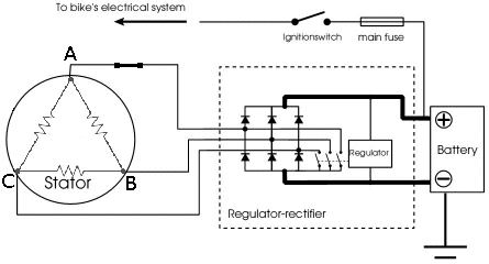 | ||
Timebandit |
Standard operating condition utilizes 3 different circuits: AB: 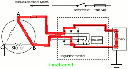 AC: 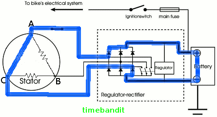 BC: 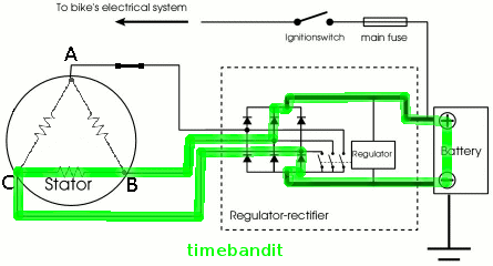 | ||
Timebandit |
The charging system harness is hard-wired to interrupt one specific lead on the stator. It's shown as Lead A in the diagram. When the switch on Lead A opens, current through circuits AB and AC are interrupted, leaving only circuit BC able to conduct current to the regulator: BC:  | ||
Timebandit |
Because this is a three-phase generator, knocking off one lead disables TWO legs of the stator, not one. There is no way around that, it's either 3-phase or 1-phase. Single-phasing results in a decrease in the stator's current output by 2/3. http://www.badweatherbikers.com/cgibin/discus/show.cgi?tpc=290431&post=2217833#POST2217833 One phase of coils continues to operate while the other two coils are quiescent and act as heat sinks. I use "pit" as a colloquial term to describe the low-output area in the current vs. RPM graph in which the stator is single-phased. If you plot current output vs. RPM, it literally looks like you've fallen into a chasm when you enter the switching band. 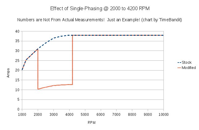 What's interesting is that the harness' most basic logic is to switch off 2 legs of the stator between 2000 and 4200 PRM, so that the stator isn't operating at full output when the RPM and oil flow are low, and presumably when the bike isn't moving very fast and there isn't much airflow across the cooling radiators. At idle, you still get full output, and at high RPM you still get full output. When you're in "the pit" charging system output is markedly reduced. This suggests that you won't get much battery charging if you habitually ride in the low-output zone, and that you can get good charging output by routinely transitioning out of the pit. (Message edited by timebandit on May 23, 2012) | ||
Timebandit |
The technicals for all of this have been hashed out over and over in LOTS of detail in the forum threads. It's a good idea to review them if the info this thread is at all unclear. Here are some links that may be helpful: Gemini's Switching Parameters: http://www.badweatherbikers.com/cgibin/discus/show .cgi?tpc=290431&post=1907255#POST1907255 Single-Phasing: http://www.badweatherbikers.com/buell/messages/290 431/665120.html http://www.badweatherbikers.com/buell/messages/290 431/679380.html Relay Operation: http://www.badweatherbikers.com/buell/messages/290 431/665057.html http://www.badweatherbikers.com/buell/messages/290 431/663672.html | ||
Jdmagri |
Just wanted to give the update. I have made the following upgrades. -Rewound Stator by Rick's with higher temp wire option -Modified rotor from EBR with oil cooling -Left the harness upgrade with relay alone, still operating I have not put a new VR on yet, as I've never had any problems with mine. I've got about 800 miles on everything so far and it all seems to be working well. I'll have a couple thousand more in the next few months so I'll keep everyone updated. Should I be looking at making the VR upgrade pretty soon or can the stock ones survive quite a while? | ||
Sparky |
I believe the stock VR should work OK long term as long as the harness upgrade relay is maintained, meaning replaced periodically. I'm saying that because my original VR lasted approx 9000 miles before showing the signs of over-volting and soon after, constant failure. Before it had failed though I had noticed that its heat sink would get extremely hot while riding around town. Nowadays with the relay installed, the VR seems like it barely gets warm, so I'm sure that the heat it has to dissipate without the relay is what causes the original VR's eventual demise. I'm at approx 5000 miles and counting with the stock VR and relay and it's still doing fine although I replaced the relay once. At approx 1000 miles ago I also had EBR's oiling rotor installed so I'm relying on that install to keep the stock stator alive. I'm sure you'll be OK with your other mods safeguarding the stator. Keep us posted if there's any change in your charging system's reliability. | ||
Sas_quatch |
@jdmagri- I'm guess since you did all this on your own that HD customer service didn't come through? | ||
Buellhusker |
I have done exactly the same as jdmagri when my stator burned out. -Rewound Stator by Rick's with higher temp wire option -Modified rotor from EBR with oil cooling -Left the harness upgrade with relay alone, still operating. Not many miles on it yet, but planning on a longer ride this weekend. | ||
Tbowdre |
MIne has about 10,000 miles with a custom rewind stator, compufire R/R, and no relay circuit. I did an oil change and noticed pieces of epoxy in the screen. My rotor was falling apart! So now I just installed an EBR modified rotor. Has been and continues to charge normally | ||
Figorvonbuellingham |
Are you sure it was epoxy? I only say this because I read about a recall where the timing chain tensioner breaks down and parts of it end up in the oil screen. | ||
Tbowdre |
yep, I am sure |