| Author | Message | ||
Stretch4201 |
ok stator failed recently on my 09 cr should i got a 08 stator and rotor or get 09 stator and the ebr rotor or rewind the stator and get ebr rotor all comments and suggestions are appreciated | ||
Dannybuell |
$$$ no issue? An 08 stator with an 08 rotor that has had the EBR oil jet modification with Hildstrom's vents (http://hildstrom.com/projects/buellstator/index.ht ml#rotormodification). A cycle electric voltage regulator with high tech heat sink and aux fan cooling, powering a SHORAI LiPo battery. | ||
Pwillikers |
Stretch, did you have the "harness upgrade" installed? How many miles ago? How many miles on the stator? Were I you, I'd rewind it and send my rotor to EBR for machining. | ||
Timebandit |
There are lots of anecdotal approaches to the stator problem, but unfortunately at this time none of them are backed up by solid scientific comparisons that accurately quantify how much temperature improvement they actually provide. Until that sort of data becomes available, we all have to pay our money and take our chances on what we think will work best. EBR is recommending the oiling rotor modification with the 2009-style stator, and they aren't offering the 2008-style kit anymore. EBR isn't using the 2008-style kit on the 1190RS. Personally, I think that puts an end to the belief that the 2008 setup is better. As far as DIY rotor modification goes, I am reluctant to drill into my rotor using a drill press without having the rotor professionally balanced afterward. I think any subtleties in misbalance would take their toll on the motor over time, especially since I'm someone who rides in the upper RPM range most of the time. Given the data that's available now, my approach was to go with the EBR rotor mod and a 2009 stator. (Message edited by timebandit on May 07, 2012) | ||
Stretch4201 |
i bought the bike in feb i was told that the previous owner upgraded the harness stator was rewound last year and at that time was when he he said he beefed up the wires in the harness | ||
Stretch4201 |
new stator or rewound? | ||
Dannybuell |
how long do you plan on owning the bike? | ||
Timebandit |
I'm not quite sure I understand what the previous owner could have done to "beef up wires in the harness." DIY modifications worry me, because most people don't understand how the harness is supposed to operate. The wiring harness doesn't need to be modified. It should have worked fine as it was, without any modifications. The fact that the stator failed after someone "beefed it up" is very suspicious. Since your freshly rewound stator failed, I'd be worrying that the harness has been modified to the point that it isn't working the way it's supposed to. There's no reason for a stator to fail in one year. The fact that it did fail tells me that the harness is bad and/or that the rewound stator wasn't very well made. I'd check the harness to make sure the operation of the circuit hasn't been modified; I'd verify that it works like the stock harness upgrade is supposed to work. I'd also check the relay to make sure it hasn't failed. I'd try to find out who rewound the stator and I'd be sure to buy the next one elsewhere. I don't understand the question about how long you plan to own the bike. This is a major reliability problem, and I'm one of those guys who would fix the problem right, regardless of how long you plan to own it. You don't want to get stranded somewhere by a cheap fix. Just my two cents. | ||
Curve__carver |
Msrp on an 08 rotor is steep. I have a used one I'll sell for $100. | ||
Stretch4201 |
Im planning on keeping this bike I rlly like it want to get it running so it is reliable. What all does the harness upgrade do I'm going to get ahold of the previous owner today and find out what exactly what was done to the harness | ||
Timebandit |
The stock stator produces three-phase electrical power. Think of it as producing alternating current power, where the voltage that you get is proportional to your RPM. (It's about 120VAC at redline.) Because there are three different sets of coils in the stator, it produces three different "sets" or "phases" of AC power. The power comes out of the stator on three wires, and you'll get alternating current if you measure voltage across any two leads while the bike is running. The harness/relay functions as a switch that is controlled by the ECM. Under low to moderate RPM conditions, the ECM tells the relay in the harness to "open", switching off one of the wires. With three phase power, interrupting any one wire will actually shut down two of the three sets of stator coils, leaving only one remaining operational. When the switching takes place, that effectively turns of 2/3 of your stator. The problem is that the stators get really hot under operation. the basic idea behind the harness is for it to shut down 2/3 of the stator at low to medium RPM, so that the stator doesn't heat-up during those conditions where there is not a lot of airflow across the radiators and oil cooler. Here is a picture that I drew to explain the concept a few months ago. The BLUE line is a plot of current output by the stator in the stock configuration (without the harness). The ORANGE line is a plot of current output by the stator when the system has the harness update. Notice that with the harness update someone at idle gets full charging output, someone lugging around town at 3000-4000 RPM gets diminished charging output, and someone who is riding the bike at higher RPM gets full charging system output. 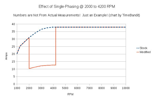 What this tells us is that the stator gets 2/3 of it's output shut down to prevent the formation of excessive amounts of heat at those times when the bike (presumably) isn't going fast enough to have good cooling. You don't want to spend all of your time in the pit, or your battery could become chronically depleted. The numbers on the Y-axis are just rough estimates. HTH. | ||
Reepicheep |
Just one minor addition... it might be airflow across radiators and oil cooler, it might be lack of lubrication contact volume (as the oil must transfer the heat from the rotor to the oil cooler and coolant). Its probably both. TimeBandit knows this 10x better than I do, but for others, you can nicely model heat transfer as a set of series resistors. The more "resistance" (thermal barriers) you have, the slower the "current" (heat) can flow through the circuit. So in this case, coil to air thermal resistance is very high. Coil to hot oil bath resistance is medium. Coil to cool oil bath resistance is low. Thus the addition of the oil passage in the crank in the EBR fix... put more and cooler oil over the hot coils. And of course if your radiator and oil cooler can't get the heat out to the air, the oil can't get the heat to the oil cooler or radiator, so the heat stacks up in the stator no matter how fast you circulate it. (Message edited by reepicheep on May 07, 2012) | ||
Timebandit |
You're right. I always leave out the part about oil flow inside of the engine being dependent on RPM, because it complicates the explanation about what's happening to the stator. Since the stock stator is actually dry (not directly oiled for cooling), oil flow has an indirect effect on stator temps, rather than a direct effect. The fact that the stator is trapped inside of the rotor in a dry "hot box" means that there's no good way to remove heat from the system. The stator generates it's own heat internally, in addition to having lots of heat radiated/convected at it by the crankshaft and rotor. So the stator gets hit with a double-whammy of heat. Heat comes from several sources, and there's not much way for heat to get eliminated. That's why we see Hild's plots of stator temp where the stator temp continues to rise until it's as hot as the other hot parts of the engine. It helps to look at heat transfer in terms of some of the different mechanisms that are available: Heat loss can occur via conduction, convection, radiation, and evaporation. The specific heat of air is pretty low (resistance to heat transfer is very high); because there's not a lot of air exchange inside of the rotor vs. outside, there isn't much opportunity for convective cooling. Without LOTS of air exchange, convective cooling can't help us. Conductive cooling is limited to thermal transfer from the stator to the ignition cover. The ignition cover doesn't have much mass, but it does get a decent amount of airflow at speed. Radiant cooling from the stator probably doesn't happen, because the gradient for heat is from the engine/crankshaft/rotor to the stator. In the stock configuration radiation probably results in heat transfer to the stator, rather than away from it. This leaves us with evaporative cooling. To the extent that any oil hits a really hot, uncooled stator, the stator can transfer heat to the oil by conduction, and to a much lesser extent by evaporative heat loss, as oil has a very high boiling point and doesn't evaporate at the bike's working temperatures. What about modifications? Putting vents into a rotor to facilitate air exchange could result in convective cooling if there's enough cool air in other parts of the motor to be exchanged with the air in the rotor compartment, and if the volume of exchanged air is high. The problem is that the thermal images of heat in the engine demonstrate that the radiant/conductive heat from the combustion chambers is so high that it doesn't look like there's cool air anywhere inside of the motor. This form of heat transfer would be pretty ineffective, because the thermal resistance of air is high / specific heat of air is low. Oil cooling, OTOH, is very effective. Liquids have a much higher specific heat, and conduct heat much more rapidly. So if you squirt oil on a hot stator, the oil is going to carry away heat into the oil sump (conductive heat transfer), where it will be pumped to the oil cooler for forced air cooling. I can see a HUGE potential to lower stator temps using the oiling rotor. Using a textbook approach from a heat transfer course, the math gets pretty complicated. But it all boils down to (pardon the pun) is that liquids conduct heat away from a stator much better than air, so liquid oil cooling is the best answer. The math makes it hard to imagine that adding a few vent holes to the rotor would make a significant difference. Direct contact with fluids is a far more effective way to transfer heat, which explains why EBR is offering the oiling rotor. | ||
Reepicheep |
I'm always nervous about trying to guess at what would be dry and what would be wet when you have "spinny things" in an oil bath. I've not been inside an 1125, but on an evo motor, the chain is in the oil bath, and is flinging a boatload of oil everywhere (including the top of the primary chamber). And there is plenty of room behind the spinning rotor for that oil to work its way into the rotor. I have no idea how much, or how to model it. Clearly though, if you are pumping oil out the crank into the stator and you have a spinning rotor, you are moving decent amounts of oil. Like you say, the fact that the measurements show the stator and the motor equalizing over time means the stator is not getting a lot of cooling oil. Otherwise the stator temp would be between the motor temp and the oil temp. | ||
Timebandit |
on the EVO that primary chain compartment keeps everything swimming in chain lube. as i recall, the EVO fill directions specifically tell you to add chain lube to a specific level on one of the flywheels, so that the bottom 1/3 of the spinny thing is immersed in oil. The result is that chain lube flies everywhere. You've got rotors, flywheels, and chains that all pass through the bath on the bottom portion of their travel, and throw it everywhere as they spin. I think that's the reason that HD stator failures are relatively so uncommon. the liquid oil bath keeps everything cool. The helicon motor has a baffle inside of it that acts as a splash guard between subcompartments, and the rotor fits so tightly over the stator that it effectively shields it from any oil splash. You can tell that the stator is staying dry by taking the ignition cover off right after a ride -- there's minimal oil in it, and the stator stays pretty dry with the stock (non-oiling) rotor. with the oiling rotor, there's a lot better oil dispersion. | ||
Sparky |
Time, I disagree with your assertion re: "...switching off one of the wires. With three phase power, interrupting any one wire will actually shut down two of the three sets of stator coils, leaving only one remaining operational. When the switching takes place, that effectively turns of 2/3 of your stator." I believe that you are only thinking of the charging system as the stator alone in which case your premise would be valid. But the stator is really connected to a Voltage Regulator/RECTIFIER which provides a circuit for each set of phase/coils to conduct current independently of each other by way of two sets of diodes. The diodes provide a DC current path for each phase/set of coils to produce current independently even if one set open circuits at the stator. The result is, I'm saying, that when the relay open circuits one phase, there are still two phases conducting current. | ||
Ljm |
Matt, Just to insert an answer that is not a comment of the nature of the universe: go with an 08 rotor, stator. Most of the 1125's out there are 08's, no stator failures, or at least few. Mrs.and I have four, no electrical problems yet, varying mileage, some cold weather bikes, some hot (AZ). Clutch weep, of course. Electrics, no. Otherwise email EBR and ask what they think. They are great folks. If you talk to your HD dealer, they will forever have you in the harness, stator, regulator replacement loop with no improvement, perhaps other than their bottom line. My .02 LJM | ||
Hildstrom |
The air cooling rotor modification is discussed in in this thread. If we'd like to speculate on its effectiveness, I suggest we do it there. | ||
Nightsky |
Three wires come from the stator: A, B, C. Current flows between AB, AC, and BC to the regulator and back. If you cut A, current now can only flow BC. That disconnects 2/3 of the stator. | ||
Sparky |
Night, you're partially correct re "Current flows between AB, AC, and BC to the regulator and back..." But it's not as simple as "If you cut A, current now can only flow BC." Let me explain it again like I did in last year's post:  ref http://www.electrosport.com/technical-resources/te chnical-articles/how-motorcycle-charging-system-wo rks Look at the circuit diagram (assuming it's typical for the 1125) at the two sets of diodes in the regulator/rectifier - that's the key for understanding how current flows from each phase/coil to the regulator/rectifier/load and back to the phase/coil producing current. Ref, repost for the following explanation here but detailed a little more clearly as follows. Trace the current path for one of those coils, say the vertical one, -- out thru the first diode on the upper set of diodes, -- to the battery +, -- thru the battery and out of the batt -, -- back to the regulator/rectifier lower set of diodes, -- thru the right lower diode, -- thru the 8 o'clock phase/coil, -- to the common return point of the coil that produced the current pulse, -- ALSO note that the middle lower diode sends a current return path -- thru the 4 o'clock phase/coil, -- to the common return point of the coil that produced the current pulse. As you can hopefully see, each phase/coil can produce current out to the battery/load independently even if one of the phase/coil wires from the stator is open circuited. Thus, do you agree that two phase/coils can produce current even if one of the phase/coil wires from the stator is open circuited? | ||
Hildstrom |
Sparky: Our 2009 stators are delta, not Y. (Message edited by hildstrom on May 09, 2012) | ||
Timebandit |
Delta, Wye, doesn't matter. This is turning into a farce. | ||
Dannybuell |
Civility encourages my listening skills. Ad Hominem does nothing for me. | ||
Reepicheep |
Sigh. You guys are worse than my kids. Timebandit, we understand this stuff is basic to you. Most people however, and by most I mean more than 99.99% of the population, don't know the difference between delta and Y windings. And 99.999% of people won't be able to correctly interpret how current flows through a delta versus Y winding though a series of diodes. So to declare it a farce seems factually incorrect. There are less than 100 people on this thread, it is not a farce that you would have to explain the difference, it is a virtual statistical certainty. Dan, your post was even worse than Timebandit's. At least he had a factually correct and relevant statement before he became tedious. You just went straight to tedious without adding anything except your opinion on Timebandit, which, frankly, we *all* already know and are sick of hearing repeated. Sigh. And now I'm carping at you both instead of adding anything. I think all three of us should be banned for a week... | ||
Nightsky |
Even imagining a wye, (it's a delta, but they can be modeled electrically equivalent) each winding gets used twice when all 3 terminals are connected for a sum of 6. Disconnecting one leg completely, shuts off one winding, and the the other two only get used once, for a sum of 2. 2/6 = 1/3 | ||
Timebandit |
Sparky, I looked at your post from a year ago. It looks like you cut and pasted the exact same content from a year ago into this thread. Bextreme04 gave you the right answer a year ago, but that doesn't seem to have effected your conceptualization of the problem. It sounds like you rejected his answer a year ago, just like you're rejecting my answer and Nightsky's answers now. Consider this: Bextreme04, Nightsky, and I all looked at the same problem independently of one another and we all came up with the same answer. Maybe, just maybe, rejecting the consensus of opinion is a bad idea; it looks like (n-1) engineers are all in agreement on this subject, and you're the only outlier. | ||
Sparky |
Time, so you don't agree with my circuit analysis it seems. I didn't agree with those who differed from my theory last year because none of the explanations included the rest of the charging system, seemingly focusing on the stator alone. I would respectfully appreciate it if you could explain your (popular) version of current flow then using the diagram I provided, disregarding the wye vs delta difference for now, and yes, it doesn't make a difference. Honestly, I don't mind being shown where the correct current path goes if it's based on fact and not what seems logical. | ||
Timebandit |
Using your diagram, which is a Wye and not a Delta: The first thing that one has to realize is that the stator is not populated by coils A, B, and C by themselves. By themselves, Coils A, B, and C do nothing. In the Wye configuration, a minimum of TWO coils have to be connected in series in order to make a circuit. In the stock configuration then, the three circuits are formed by Coils A+B, B+C, and A+C. This is your diagram with the harness switching relay added. It interrupts the peripheral lead to Coil A:  When the switch opens, all of the wiring associated with Lead A is functionally removed; the only circuits that remain in the charging system are these:  When you remove the wires associated with Coil A, only the leads to coils B and C remain. Coil A is no longer available to participate in any circuits. One way to look at this would be as if it's an airplane propeller. You have 3 blades, you take away one, and you have 2 left, leaving you with 2/3 power. That's a simple way to address the problem, but it doesn't follow the logic necessary to trace the functional circuits. Another way to look at the problem would be to trace the active circuits. When all three circuits are functioning, you have: 1. Flow across Circuit AB. Coils A and B add up together to make ONE circuit. 2. Flow across Circuit AC. Coils A and C add up together to make ONE circuit. 3. Flow across Circuit BC. Coils B and C add up together to make ONE circuit. If you take away Coil A, then Circuit AC becomes DEAD, and Circuit AB becomes DEAD. Only Circuit BC remains. Only 1 of 3 circuits remains. That's a 2/3 power loss. Maybe the confusion comes along because you look at coils A, B, and C as if they are independent circuits. They are not. They are only components of circuits AB, BC and AC. What you really need to do is to count circuit loops, not coils. When the wire to A is connected, there are three loops. When the wire to A is disconnected, there is only one loop. (Message edited by timebandit on May 10, 2012) | ||
Timebandit |
Stock configuration has three circuits: Circuit AB:  Circuit AC:  Circuit BC:  When you interrupt Wire A, only one circuit remains, BC:  You've lost 2 of 3 circuits, and 2/3 of the output power. | ||
Nightsky |
It's no wonder these stators are failing. They've got colored ink on the windings. |