| Author | Message | ||
Dualbuells |
Timebandit - if your thinking of mounting under the head of one of those torx bolts, I think that could work, bring it out of the case with the wires at the top. Our engr is out till tomorrow see what we can do then. | ||
Timebandit |
that's exactly what i was thinking. mount it under a torx bolt, rune the wires out behind the stator with the rest of the wires. | ||
Dualbuells |
Timebandit - I can build sensor,I'll need stud size for ring terminal to fit Torx bolt and length of probe to bring it outside the housing by couple inches and clearance, with a 6 - 10 ft lead wire. I can purchase a datalogger at 30% discount from Omega P/N OM-PLT2 for a single point, datalogger & software for around $120.00 Let me know what you think. I'm sure I'm living on borrowed time on my 09' CR, since it has 4K miles on it only a matter of time for mine to go! | ||
Timebandit |
Thanks for your interest in the problem. As I think about this some more questions are coming up. Here's where I stand right now: 1. I can look at the stud size. If I had to guess from memory, I'd say it's an M6 bolt. Will look into this. 2. As far as lead length goes, I'd say it would have be equal to stator lead length and then some, considering that we need to hid a logger somewhere on the bike. Problem is, I don't know stator lead length. Anybody? Knowing the physical size of the logger would be helpful, as size will define placement. I'll try to look up the spec sheet for the Omega part. If you've got a link, that would be better yet. Price you mentioned is not scary. 3. Is there a downside to making the leads extra long, and coiling them up? 4. Is it possible to connect the interface terminals for the logger to the probe wires after passing the wires through the wall of the ignition cover? Looking at my cover, It looks like a small hole would have to be drilled in the rubber grommet that the stator leads pass through, to accommodate the lead wires. The smallest possible orifice would be best. That would mean passing a wire without connector fittings, and crimping the fittings on after installation, if that's feasible. 5. Would it be possible to mount two probes on the stator? I have a theory that would require testing differential temperature at two points at opposite sides of the stator. 6. I've looked at a lot of stator pictures but I need to see more. I took surveillance pics of my perfectly fine stator at 4100 miles out of morbid curiosity. I didn't like what I saw. It had the characteristic 2-tone discoloration that we always see, but it's color was lighter than in most pictures I've seen. Maybe that's because other people took their pictures when there was a stator problem. I was looking at the stator while I was inside to replace a perfectly good rotor. I'll try to find that pic. | ||
Timebandit |
http://www.omega.com/pptst/OM-PL.html | ||
Nightsky |
If you used #22 magnet wire for probe leads, you probably can squeeze around the grommet without altering it. | ||
Timebandit |
When you talk to your engineer, ask him the following questions for me. I'm thinking your temp probes will be producing a low DC voltage output at low current, correct? Just want to make sure we won't run into any inductive interference from proximity to the high voltage/current AC stator wires coming out of the case. I'm thinking that each lead pair would have to be twisted tightly so there are no big magnetic loops. I don't know what kind of material you use for the leads, but using magnet wire would allow the two leads to hug each other tightly. | ||
Timebandit |
Nightsky, have you looked closely at the rectangular grommet that the stator leads pass through? It's hard for me to imagine fitting 22ga wires in there. I'm thinking that some of the rubber might have to be "relieved" to accommodate them. | ||
Dualbuells |
Timebandit, I see you found the link,(http://www.omega.com/pptst/OM-PL.html) I can get the datalogger with two inputs no problem, just a little more money, which I don't mind spending in the least. I was thinking it could be cable tied under the passenger seat area, so a 6ft (or 16ft) length is good, coiling extra wire is not a problem for the t/c wire. The sensor I planned on mfg is 1/16" dia ungrounded MI cable Type J with 304SS sheath with a ring terminal brazed to the tip for good heat transfer, we could leave it off and crimp it on after the install through the rubber grommet. We can go to .040"dia probe if space is an issue it is a little more fragile, but I can't imagine the 1/16"dia a problem. I'm thinking we can make the probe 12 - 15" length the extra above is no problem can be cable tied to frame etc. anything. the lead wire will be 24awg. stranded with mylar shield and a drain wire for grounding and electrical noise isolation. If you need a "spec drawing" of the sensor I'll work up our part number and send you something. I think that covers your questions. PM me if need be. | ||
Dualbuells |
The t/c generates a dc millivoltage, @ 200 deg.F it's 4.9 millivolts, 300 deg. F it's 7.9 mv, roughly. The wires are twisted pairs, unfortunately we are out of stock on stranded, only have solid 24 awg. We can slide a pc. of Teflon tube over the probe after insulation (good to 600 Volts)to prevent electrical shorts. Making the junction ungrounded also isolates the juction and datalogger from electrical shorts. The thermocouple lead wire measures 0.098" | ||
Timebandit |
I had originally thought that if we just wanted to get a peek at oil temperatures, all we'd need to do would be to mount a sensor in a convenient place, and the hub of the stator looked like as good a place as any. Now I'm thinking about a more complicated theory. Every stator photo that I've ever seen has showed a stator that is burned on one side but not the other. Now I'm thinking that Zack's idea could provide some really useful information if we were able to mount two probes on the coils themselves. One thing that I've noticed that nobody has ever talked about is that all of the stators always seem to be burning the exact same coils. To really appreciate this, you need to take everyone's photos and rotate them into the same orientation for comparison. To me, it looks like everyone is having the exact same problem -- the exact same coils are getting burned in every stator. It would be very helpful to be able to determine the temperature of the coils that are failing, and compare that to the temperature of the coils that are not failing. Knowing that temperature differential will tell us how much temperature reduction is necessary to protect the stator. To get this answer, mounting on opposite sides of the hub may not be good enough. What we really need to do is to mount on stator poles. Can you think of a way to attach a probe to one of the poles? I'd like to measure on two opposite sides, in the 10:00 and 4:00 positions as you're looking at the rotor with the cover off. That would be 2:00 and 8:00 if you're looking straight at a stator in a removed cover, after it's been rotated so that up is up. | ||
Timebandit |
FYI my bike is bike is consistently ridden on a 120 mile sport riding loop. the daily trip involves a 20 mile ride pushing the 70 mph speed limit at medium RPM on highways to reach my favorite spot. the sport part of the ride consists of 80 miles balls to the wall, 6k to 10k. the ride is then terminated by the 20 mile conservative ride home. i had the harness update installed with 200 miles on the stator, and put 4000 miles on the stator in 6 weeks. this is what a new stator looks like when you ride like a bat out of hell for 4000 miles in 6 weeks. 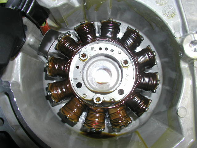 notice the asymmetric heat distribution. at least the stator lasted longer than the tires.  (Message edited by timebandit on January 17, 2012) | ||
Dualbuells |
My stator cover needs replacing due to road rash after a friend crashed it. I'll remove it this weekend and see what can be done to attach sensors to the poles at said location. Do you know if in this huge link there is a photo location to review and confirm your findings. Our electrical tech is going to look through link for info and will check out my stator when I get it off this Friday after work. | ||
Timebandit |
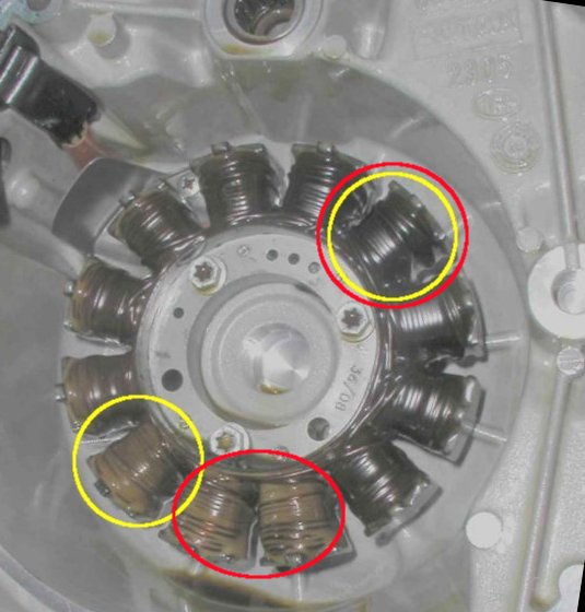
I haven't been able to consolidate all of the stator photos in one location, if that's what you're asking about the "link". Doing that would really be helpful. I've had to spend an evening browsing for stator photos to find them all. FYI, a friend of mine took one of my stator photos and did some image manipulation, using gamma correction to make the heat discoloration differences more obvious to him. He claims there's an improvement when he looks at the pics on his monitors, but I don't see it on mine. Here it is in case it helps anyone. I've marked the coils that I think would be particularly helpful to compare; specifically the one by the date stamp on the case and the one opposite to it (Yellow). Might be even better to compare the one by the datestamp to the one on the bottom (red). What we really want to compare is the hottest location to the coolest location, not necessarily locations that are on opposite sides of the stator. (Message edited by timebandit on January 17, 2012) | ||
Timebandit |
 | ||
Timebandit |
i started a thread to try to assemble a collection of stator photos in one location. hopefully people can help us out. http://www.badweatherbikers.com/buell/messages/290 431/665334.html | ||
Dualbuells |
good idea, a thought, perhaps a dumb question but does the oil get injected or splashed over the coils. wonder if the coils with lighter color are subject to increased oil flow. | ||
Timebandit |
here is what i'm thinking: the oil is not sprayed or splashed on the coils with the stock rotor. the rotor fits very tighlty around the coils, trapping heat inside of the stator. the coils at the bottom look like they get some exposure to oil. the remainder of the coils dont. if the tip of the rotor catches some oil, it carries the oil upward while it's rotating, dropping oil on the coils in the back. that would explain why the coils on the bottom, and those toward the bottom rear, appear less discolored than those that are on top and facing the front. oil is pretty viscous, and inside of the rotor i think there's a wave of oil going from the bottom up slightly towards the back. there's not much if anything in the front or top. the oil-jet mod would change this. i'm pretty convinced after looking at all the photos that the coils by the word "ROTAX" are the ones that always get spent, and the ones that get exposed to the oil wave are the ones that get protected. it would be really interesting to measure the temperature differential between them. | ||
Timebandit |
in most cases it appears that the discoloration goes on long enough that the difference between these zones becomes less discernible. the only reason that it's so evident on my stator is because i took the bike apart to examine it when it had low miles on it and nothing was wrong. i performed an early surveillance check, and caught the discoloration early, when it was appearing in the worst place first and hadn't spread over the entire stator, and the difference was striking. with high miles, i'd expect the tan portions to go away and become colored like the dark brown zones, and for the dark brown zones to become darker still. eventually, everything will brown out from the heat and the stator might look uniformly dark. (Message edited by timebandit on January 17, 2012) | ||
Nightsky |
You want to place your thermocouple such that any wire loop inside the sensor or between sensor leads is perpendicular to the rotor cylinder. You do not want magnetic lines of flux cutting the area of any loop. Any loop of the sensor will be correctly placed if it's at right angles to the stator windings. Stator windings are positioned to get max lines of flux by design. | ||
Timebandit |
Do you know if in this huge link there is a photo location to review and confirm your findings. I've asked people to post stator photos in that other thread. http://www.badweatherbikers.com/buell/messages/290 431/665334.html So far we have 5 samples, and 5/5 show the same burning pattern. So far 0/5 stators support the null hypothesis. Nightsky, you're the statistician. How many identically colored stators does it take to prove statistical significance? | ||
Dualbuells |
I plan on tearing into mine tomorrow evening, so I'll add my photo's to the link. I had a boss that always said "a sample of one is a sample of none" but 5 out of 5 is a fair sampling IMHO ! | ||
Timebandit |
don't forget to disconnect the battery. easy step to forget, disaster if you crank the motor. | ||
Timebandit |
You want to place your thermocouple such that any wire loop inside the sensor or between sensor leads is perpendicular to the rotor cylinder. You do not want magnetic lines of flux cutting the area of any loop. Any loop of the sensor will be correctly placed if it's at right angles to the stator windings. Stator windings are positioned to get max lines of flux by design. in other words, the poles of the stator are mounted radially, so that each one is oriented on the cylinder as if it were a ray extending outward from the center of the circle. the wires in the windings are wrapped around those poles, perpendicular to the rays extending out of the circle. you want the loop of wire in the sensor to be oriented parallel to the rays coming out of the center of the assembly, and perp to the coils. clear as mud? | ||
Timebandit |
The more I think about this bike, the more I'd like to get a handle on oil temperature measurements. I had changed the oil on my 1125R as I put it up for the winter, but we had a few warm days this month and I got to take the bike out for 3 rides. I rode a total of 371 miles on 3 days when the AT was 57*F, 45*F and 50*F. When I dumped the oil to get started on winter maintenance, I was shocked to find that the fresh change of Mobil 1 15w-50 had already turned very dark brown, almost black. All in 371 miles over 3 heat cycles. Today I mentioned this observation to a factory expert on this motor and his response was, "The bikes are known to run hot." No kidding. But hot enough to brown out a fresh change of Mobil 1 in 371 miles??? Full synthetics like M1 are supposed to be heat stable to 450*F. I asked if they had ever directly monitored oil temps like we've been proposing here. The answer was no, they monitor coolant temps. It would be really interesting to know how hot the oil is really getting. I was surprised to see a fresh change of M1 look that bad after less than 400 miles. This makes me wonder if we might need a bigger oil cooler. | ||
Dualbuells |
installing sensors to monitor oil temps should be easy, run them through the oil plugs or where ever. whole lot easier than the stator! | ||
Dannybuell |
I think the fresher looking poles are the ones that are submersed in oil. Moving to water cooled from the S1 has been different. Since 600 miles the CR has used nothing but ester based syn, Red Line and more recently Amsoil. The way I ride the CR (<7,000rpm) it is not burning oil. I was doing oil and filter every thousand like the S1 until I realized how the oil still looked and felt good. I have been doing 3.4 quarts and filter every two thousand miles for the last few oil changes. | ||
Timebandit |
Are you noticing the discoloration I've mentioned? I've never seen M1 change color like that in any of the other bikes, including my air-cooled BMW and my air-cooled EVO. The discoloration can only be one of two things: 1. Thermal damage to Mobil 1. Unlikely. 2. Contamination. More likely. Thinking about this a little more, I think the oil is being discolored by the coating that's coming off of the heat-damaged stator wires. | ||
Timebandit |
> "submersed in oil" the lighter colored poles can't actually be SUBMERSED in oil. We've rotated the photos to show the horizontal reference for oil level as demarcated by the yellow lines. to the extent that the rotor running through the oil can pull the oil upwards (think of a cake mixer pulling cake batter), there would be a lower than normal oil level around pole 5, and oil would be pulled up to fall on the poles all the way to pole 10. technically speaking these poles aren't immersed in oil, but they have enough contact with oil dripping onto them to sink away some of the heat. the contact with oil definitely does seem to have some protective value, doesn't it? | ||
Timebandit |
Back to temp measurements: We still need to determine stator temps, so I'd like to continue to pursue that goal. Ultimately, what I'd like to measure is the temp on the stator hot side vs. the stator cold side. A third measuring point for the reference oil temp would be helpful as well. 3 measurements would allow us to quantify not only the thermal gradient between the hottest and coolest stator poles, but also the gradients between those poles and the cooling oil. If someone had one of the EBR oil-jet rotors, I'd expect to see the hot-side and cool-side stator temps equilibrate with the engine oil temp. if/when that happens, stator life is maximized. Dualbuells, is there a 3-channel data logger? Did you make any progress taking your bike apart over the weekend? |