| Author | Message | ||
Guambra2001 |
Well let me start of by thanking you guys in advance, I need some help installing an alarm system and a "quiet core" on my FMF pipe. I do not have any electrical or mechanical abilities but I was successful enough to do the following mods: 1. De-noid 2. HID installation on Low beam 3. Toggle ON/OFF switch for HID (took me a while but I figured it out) 4. Buell Accessory 12v plug installation 5. And integrated LED brake/turn signal along with new brake/clutch levers. Installing all these mods may not be like much for some of you guys but its a real accomplishment for me. And with this being said, there are two things that are standing in my way of completing my mods (at least for now). 1. Installing my alarm system that also has a remote start and. 2. Installing a "quiet core" for my FMF pipe because its a little loud. So my questions for you guys are: 1. How do I install this alarm system? I've tried following the directions but I'm not sure where they want me to splice or connect the wires. Specific places where I can find the wires I need to splice or just general help I guess. Here are the Pictures so you guys know what I'm talking about.  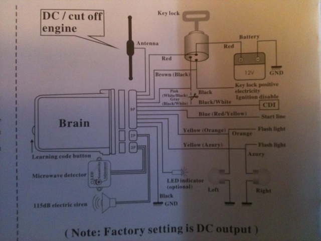 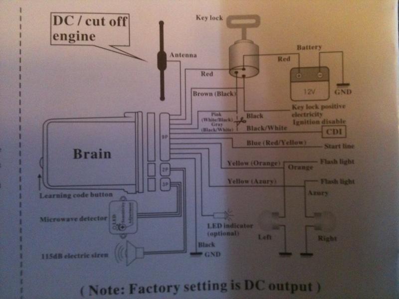 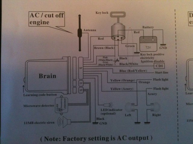 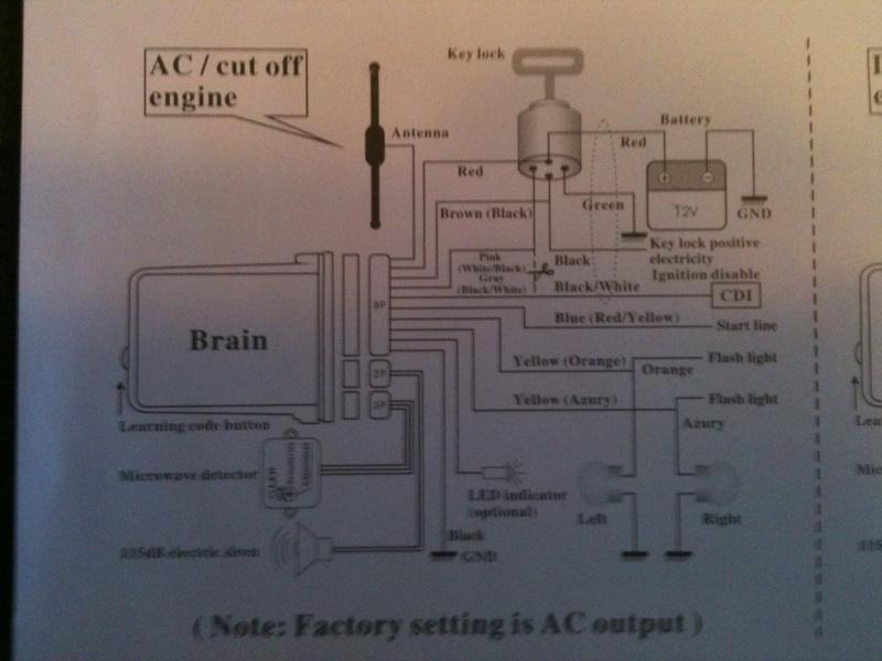 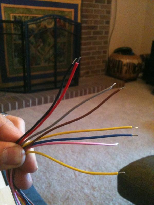 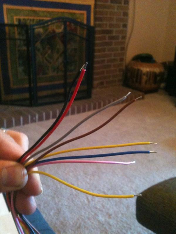 2. How do I install the quiet core on the FMF pipe? Is there something I need in particular? A tool or maybe some sort of high temperature sealant? Here are some pictures so you know what I'm talking about. 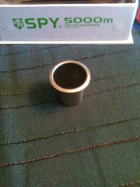 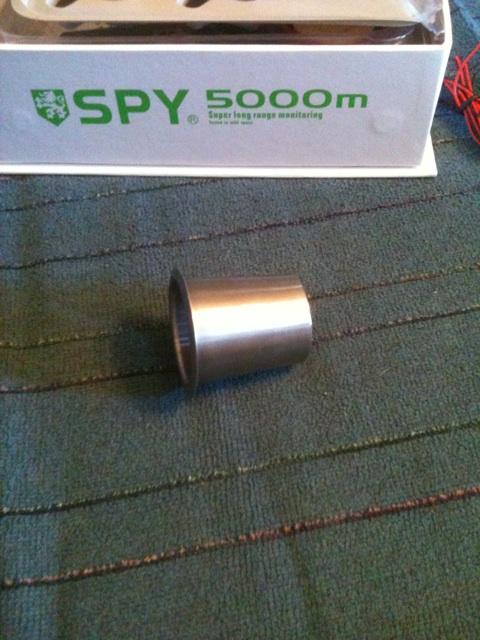 So sorry for the long post but I'm a little frustrated on trying to figure this thing out. Thanks for the help and suggestions. | ||
Nuts4mc |
FMF help line: 310.631.4363 call them - there are two styles of exhausts (complete system and a slip on) built by FMF for the 1125r - you need to know what you have before you call them - they have some pix on their site on how to re-pack their mufflers - the pix/dwg may help you figure it out on how to git er done. (looks like you have to remove rivets and end caps in order to "slip in" the quiet core)...have to have a "pop rivet tool"...the Air Force has lots of rivets - you may seek help from someone on the flight line.... I've done scorpio alarms for some of the young'ens...the instructions are usually model specific so color codes are "matched up" correctly - suggest you get a 1125r Repair manual to get hold of a wiring diagram...and again find a flight line mechanic to help you get the electrons flowing in the correct direction ...Note location of the "antenna" on the alarm's "brain" is critical to it's "remote control" operation...otherwise a very frustrating "option" to get to work reliable. | ||
Motorhead102482 |
I've been working on electronics for 13 years. I'd say that wiring diagram scares me. Most of it is pretty straight forward, but the CDI portion and whatever the pink wire is supposed to go into in the ignition switch don't mean anything to me. If you need help reading any of that, PM me and I'll help you out. Chances are, an electrical book for the buell like Nuts said would definitely help you. | ||
Northernyankee |
Basically the pink intercepts the signal to the CDI and reroutes it to the brain and sends it back out on the Black/white to the CDI. | ||
Northernyankee |
Oh and for the FMF just remove the "Muffler" and the quiet core slips in, then bolt it back up. | ||
Tbowdre |
No idea on the Alarm... I use a Xena alarm disc lock for my simple brain The quiet core: 1) remove springs that attach mid pipe to muffler 2) remove bolt that attaches to the foot peg bracket 3) remove muffler and install quiet core between muffler and midpipe 4) reassemble. yes, with hi temp sealer todd (Message edited by tbowdre on October 11, 2011) | ||
Guambra2001 |
Thanks guys I installed the quiet core I'll see in the morning if it actually had an affect on sound. Thanks for the quick response. I still need some help installing the alarm but ill probably have to wait for the weekend. | ||
Guambra2001 |
BadWeb, I have come to a dead stop, I NEED your help installing this stupid alarm. I already looked in the wiring diagram and can't tell exactly what wires to split into and with which ones. I looked into the ignition switch and saw 4 wires, 2 red 1 red/gray and 1 red/black. According to the directions this is where the wires are supposed to go. I figured out that the wires coming from the alarm are: the 2 yellow wires going to the positive side of the turnsignals, red probably goes to power and black to ground. The rest I can't figure out does anybody have a clue about which wires to splice into? Has anybody installed this specific alarm or better yet installed a remote start? My electrician friend couldn't figure it out, than o dropped it off at a Harley davidson dealer and they couldn't figure it out!! So I'm out of options and requesting the guidence of some fellow buellers. Thanks. | ||
Therealassmikeg |
Ok First off...I'd say don't install this product. But since you asked Here You go... DISCONNECT BATTERY GROUND CABLE!!! Figure out where you want the ecu most likely under the pillion or seat. Most or all the wires you need to work with are right in that area. 1)RED ecu Wire goes directly to Battery Positive Lead. If you hook directly to the battery +. Make sure you put an in line fuse on this wire. OR You can find the RED/YELLOW wire coming off the main fuse box "Battery Fuse" (it's the 30 amp fuse) Attach RED ECU Wire to RED/YELLOW and no in line fuse 2)BROWN ECU WIRE goes to key on. This is the RED/BLACK wire under the fuse box. Connect BROWN WIRE to RED/BLACK ---OR--- You can access the RED/BLACK WIRE from the KEY RELAY This is the only relay with these 5 wire colors *RED/BLACK* BLACK BLACK RED *RED/BLACK* Connect the BROWN ECU WIRE to Either *RED/BLACK* Wire at the Relay 3)PINK ECU WIRE Is the Ignition cut off. This is the WHITE/BLACK WIRE the goes to the ignition relay under the seat (It's the only relay with a WHITE/BLACK wire). Cut the WHITE/BLACK wire. You will now have 2 WHITE/BLACK wires. One coming FROM the Ignition Kill Switch and One going to the Ignition Relay Connect the PINK WIRE to the *WHITE/BLACK* wire that is coming FROM the Kill Switch. 4)GRAY ECU WIRE Connect the GRAY WIRE to the *WHITE/BLACK* wire going to the Ignition Relay. 5)BLUE ECU WIRE Connect the BLUE WIRE to the *BLACK/RED* wire at the STARTER RELAY The Start Relay is the only relay with These 5 wire colors: *BLACK/RED* GREEN/ORANGE BLUE BLUE GREEN 6)YELLOW ECU WIRE The 2 YELLOW WIRES connect to the lamps you would want to flash. They are recommending the turn signals Hook the YELLOW wires to the LEFT an RIGHT Turn Signal wires. The turn signal wires are located near the tail lamp and are BROWN and VIOLET Connect One YELLOW wire to BROWN and One YELLOW wire to VIOLET 7)BLACK ECU WIRE Connect Final BLACK WIRE to CHASSIS GROUND 8)RECONNECT BATTERY GROUND GOOD LUCK!!!! Mike G | ||
Guambra2001 |
Wow, thank you very much. I'll try it today and I will keep you posted. THANK YOU | ||
Guambra2001 |
therealassmikeg, Thank you for the specific directions, I was able to install everything but the remote start function didn't work completely. I installed everything as specified, the bike cranks but doesn't turn on. With key in and in the ON position the bike will turn on at the push of the remote start. Do you have any suggestions? Maybe one of the wires needs to emulate the key ON position? Per your instructions I attached brown wire to red/black under fuse box. Pink wire to white/black coming from killswitch and gray wire to the other white/black wire. Blue wire goes to black/red wire from start button. I've done all that but the bike only cranks but does not start. | ||
Therealassmikeg |
I emailed you back w/ my phone # give me a call bud.. prolly just one wire. I did this from the etm and dont have my bike at the moment it at the shop getting some warranty work done. ****KEY RELAY**** *****This relay has 2 red/black wires. Try hooking the BROWN wire to the other red/black on that relay**** "This is the only relay with these 5 wire colors *RED/BLACK* BLACK BLACK RED *RED/BLACK* Connect the BROWN ECU WIRE to Either *RED/BLACK* Wire at the Relay " Cheers Mike G | ||
Therealassmikeg |
Trace the RED/BLACK wire under the fuse box (that you hooked the brown wire to)to the key relay. Then find the Other RED/BLACK wire on that relay and hook the BROWN wire to it. Should work... | ||
Ratbuell |
remote start on a motorcycle? Better hope nobody drops anything heavy on your shifter, notching it into first gear while you're not looking.... | ||
Blake |
In that case, wouldn't the safety interlock prevent power to starter? | ||
Therealassmikeg |
I would think that to be correct, but not once the bike is started, then anything goes... I really don't care for these crazy gadgets, I'm just trying to help where I know I can... | ||
Guambra2001 |
Therealassmikeg, Thanks for your help, I tried switching the brown wire to the red/black wire in the key relay but I noticed that the problem might be in the aftermarket power commander V. When I put the actual key in the key hole and put it in the ON position, the PCV had power but when I pressed the remote start button there was no power to the PCV and I only cranked the engine but did not turn it on. Likewise if I leave the key in and in the ON position the remote start does work, so I'm thinking it's something to do with the PCV. But I appreciate your help, without your instructions not being able to install this would have drove me crazy. | ||
Therealassmikeg |
You're welcome. You'll need to figure out which wire the brown wire hooks to I think that is the problem. Its not powering the correct circuit when activated. Otherwise the only other thing I can think to suggest is to try switching the pink and gray wires maybe you have them backwards. I'm kind of not sure at this point what to tell you. Sorry I couldn't do better from a couple thousand miles away Mike (Message edited by therealassmikeg on October 25, 2011) |