| Author | Message | ||
Dcmortalcoil |
I'm in the midst of tightening the rotor nut. I got the crankshaft locking tool (B-48858). According to the manual, the valve cover needs to be taken off to visually located the TDC based on the position of the cam lobes. I tried rotating the engine incrementally to locate the front notch on the crankshaft. I'm finding this task to be very difficult because the periphery of the crankshaft is not perfectly circular. Anyone have alternative way (without removing the valve cover) of finding the TDC to enable the locking tool to lock onto the front notch. Are there any visual markers I can use on the ignition side? Any help would be great. (Message edited by dcmortalcoil on October 10, 2011) | ||
S21125r |
pen light shining down the plug hole? Prohibitive as you'd probably have to rotate the engine so you could look down the hole... Could try using a wooden dowel as a depth gauge, just exercise a little caution so you don't have to tear in deeper to retrieve splinters  | ||
Colintornado |
I may be wrong,but it looks to me like you should be able to line up the top balancer shaft to the position it is in (TDC front cylinder)in the manual. The picture is in chapter 3 page 78 of the manual.The picture shows with marks aligned,but you wont be able to see them if the rotor is fitted. The balancer shaft is set by aligning marks at tdc so it should be possible to rotate to set the balancer to the same position by looking at the holes and recess made into the balancer gear. If you see what I mean ! | ||
Tbowdre |
Been there done that. It was impossible for my poor eyesight, poor judgement to determine TDC with valve covers off looking at the cam shafts.... even with frame off and great visibility. S21125R has it right for my situation I just pulled a spark plug and watched a length of cable move up and down while i rotated the engine... easy(er) I mean it still felt like a of a leap of faith that I was in the right spot. 300 foot pounds is a s#it ton of force to put on your crank shaft with a steel rod threaded into the middle of the engine. In the end it went just fine. Torqued the nut and the bike is back together running great, even seems a bit more quiet | ||
Dcmortalcoil |
Here�s how I�ve found the TDC center (trial and error) to enable the crankshaft (CS) locking tool to engage the front cylinder notch (see Fig. 3-61) to lock the CS (without taking out the spark plugs or opening the valve covers): (1) Remove the exhaust to access the access plug (see Fig. 3-60) for the CS locking tool. (2) Remove the air cleaner assembly to access the throttle body. (3) Take off the throttle body (loosen 4 screws to loosen the 4 clamps) (this step is not necessary, but makes it a lot easier to see the valves - otherwise hold the throttle in the open position. (4) Disconnect the stator connector (see Fig. 3-144) and pull down about 3-4� of the stator cable through the guide to give some slack. (5) Open the stator cover (see Fig. 3-148) and hang it so that it is out of the way to access the CS nut (see Crankshft Nut photo) - no need to remove the wire terminals. (6) Insert the CS locking tool and lightly tighten to see if it abut against anything (either the periphery of the weighted part or fan-shaped portion of the CS (if so loosen the CS locking tool a tad) or nothing. (7) Rotate the CS counter-clockwise (CCW) (normal rotating direction of the engine) using a 32mm deep socket over the nut while observing the front valves and piston (visible through the throttle body opening (see Valves photos), until the front cylinder valve is about fully closed - you will know because the resistance is highest at the TDC (compressing air). (8) Lightly tighten (DO NOT FORCE) the CS locking tool. If you hit the notch, the CS tool can be inserted further by about 3 turns (rough estimate - did not actually count), otherwise the tool will not turn or you will be able to fully insert the tool (not hitting any part of the fan-shaped portion). (9) Rotate the CS CCW first and then CW: (a) No rotation CCW, but rotation CW: This means that the CS locking tool is engaging the right edge (relative to Fig. 3-61) of the fan-shaped part instead of the notch to prevent the CS from rotating CCW; (b) No rotation CW, but rotation CCW: This means that the CS locking tool is engaging the left edge of the fan-shaped part instead of the notch to prevent the CS from rotating CW; (c) Rotation in both CW & CCW. (10) If (a) occurs, loosen or remove the CS locking tool to enable the CS to rotate CCW - and repeat steps (6)-(9). (11) If (b) occurs, loosen or remove the CS locking tool to enable the CS to rotate CW - you are close. Repeat steps (7)-(9), but rotating the CS CW (instead of CCW), keeping a close eye on the front cylinder valves. When you hit the most resistance while rotating the CS, insert or lightly tighten the CS locking tool. You should be locking onto the front cylinder notch at this point. Otherwise repeat steps (7)-(9). (12) If (c) occurs, and you can insert the CS tool all the way in, you hit space. Leave the tool inserted all the way in and rotate the CS CCW until you can no longer turn CCW - you are now in situation (a). 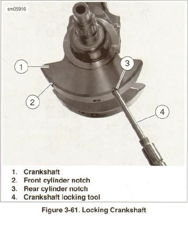 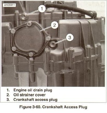 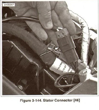  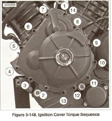 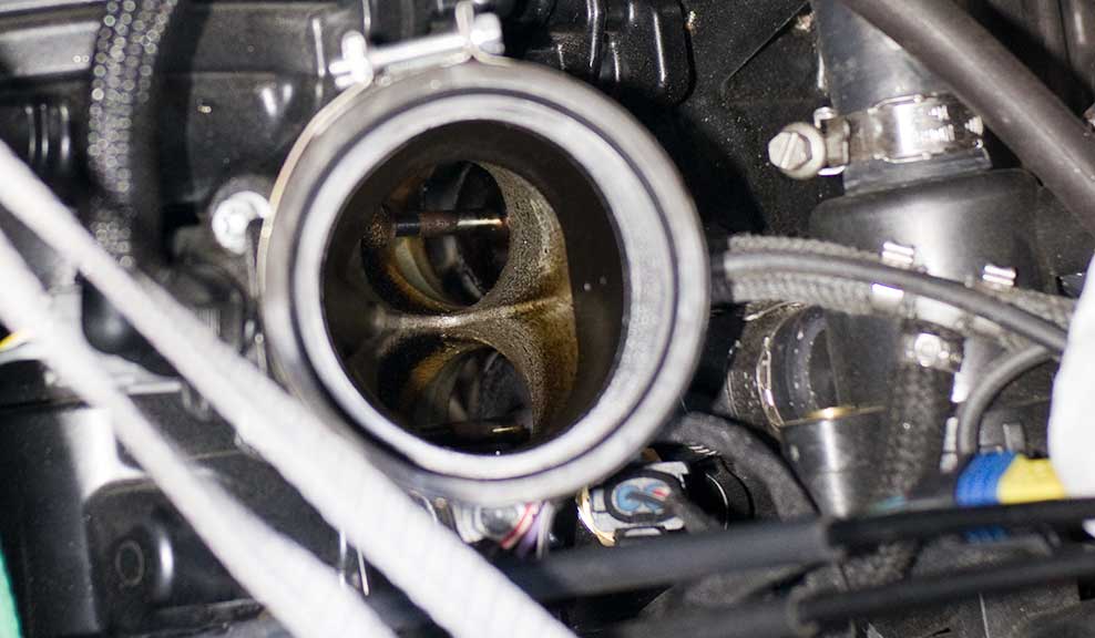 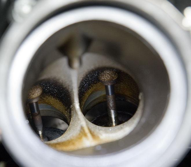 | ||
Dcmortalcoil |
The first photo showing the nut also shows the TDC position. Now I know where it is based on the third bore almost in alignment with the balancer shaft - as long as the rotor is not removed and repositioned. BTW, while I was disassembling the stator cover, I examined the stator. Here's what it looks like.  It's definitely got darker, but not that bad. Also, while I had the throttle body off, I epoxied the throttle linkages:  | ||
Green1 |
Thanks for the tips | ||
Timebandit |
> "Anyone have alternative way (without removing the valve cover) of finding the TDC to enable the locking tool to lock onto the front notch. Are there any visual markers I can use on the ignition side?" Wow -- I'm really surprised that nobody seems to know the easy way to do this. I have another way that makes the job a LOT easier: First, if all you want to do is a rotor exchange, you don't need to take the seat off of the bike or mess with the stator wires up top. All that you need to do is to remove the hall effect sensor. This leaves you with enough slack in the cables to rotate the case cover out of the way to hang it. You don't need to disconnect the stator wires topside, or slide them down like manual suggests. Second, finding the front TDC position in the crankshaft is easy. You don't need to rotate the engine forward (major asspain), and you don't need to take off any parts on top. You don't even need to remove the seat. Just remove the washer that's on the balancer shaft, so that you can see the balancer behind the washer. The balancer has a curved cutaway. I modified one of your pics to highlight the washer that should be removed: 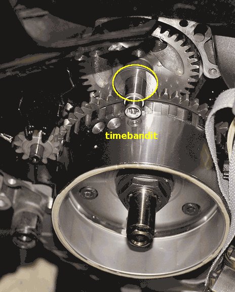 With the washer off, look for the curved cutaway on the balancer. Use your breaker/socket to rotate the crankshaft until the curved cutaway is parallel with the circumference of the teeth on the sprag clutch. (Sorry, no pic.) Doing this brings the recess in the crankshaft precisely in-line with the hole for the crank locking tool. At this point, the tool should just push right up into the receptacle in the crankshaft and you should be able to lock it in place. Verify that you can't rock the crankshaft in either direction with the breaker and you're good to go. HTH. It should make the job a lot easier. | ||
Shags |
I was wondering if you take out the oil strainer could you see enough of the crank shaft to find the notch.Just a thought. |