| Author | Message | ||
Blitzer454 |
I am one of the unfortunate ones that has had to replace a bad ECM on my 2006 Uly. It is widely know that the cause of the failure is due to the bottom of the seat making contact with the connectors on the ECM causing stress between the connector and PCB. I wanted to see if I could fix my ECM by locating the broken joints and repairing them. So I sliced the case in half using a cut off wheel in my dremel.  I then peeled the case away from the PCB. As you can see the case was completely filled with a rubber like compound. I tore off a few chunks before taking the picture just to see how hard it would be to remove the rubber. I then removed the rubber away from the connector pins on the bottom of the board.  I'm an Engineer and I have access to a lab with a nice scope and solder station. As you can see in this next picture there are cracks in the solder between some of the pins of the connector and the solder pad on the PCB.  That is just a picture of some of the bad joints on one connector. Note how the solder is cracked on 4 of the pins. This makes for an intermittent connection. The other connector had similar defects. I re-flowed the solder on all the pins and took the ECM back home for reassembly. I can honestly say that this is the worst solder I have ever worked with. It did not re-flow worth a damn. I'm sure it's lead free and environmentally safe and next to worthless. Anyway back home and with a little black tape, it's almost as good as new. Almost.  Part of the reason I am doing this is because the race ECM that I have been using has never really ran right since I put it on the bike. The race ECM was programmed for a different pipe than the stock pipe. I have done a bunch of TPS resets but that doesn't help. So if this old ECM runs better, then I going to have the race ECM re-programmed for a stock pipe configuration. Then I will switch back to the race ECM and keep the old ECM as a spare for diagnostic work when needed. I don't think I would trust it in the long run since I exposed the PCB by cracking the case open and removing the protective rubber compound. So far the bike is running normally with the old ECM back in place but the real test will be my drive back and forth to work the rest of the week.  I also relocated the ECM to prevent any future problems. | ||
Buellerxt |
Interesting analysis, Blitzer. It's really hard to see a rational for Buell putting the ecm in such a vulnerable spot, regardless of how many gallons of koolade we drink. Forget that 'it's Harley's fault' baloney. It's one of those 'Duh' moments as soon as you see it. Keep us posted for interest sake. I hope you get the race ecm worked out for your exhaust and that the 'opened' ecm keeps on chugging! | ||
Reepicheep |
Cool! Thanks Blitzer! Interesting that the solder cracked, and not the board. I never would have thought of that, but it makes sense with modern solder. I'd recommend "rescue tape" to reseal the ECM. It's a silicone epoxy stretch tape. Great stuff. | ||
Rays |
Blitzer - outstanding post. I would have honestly thought there would be lifted traces all over the place so very interesting to see the solder joints fail like that. | ||
Teeps |
That is typical PCB failure. I've seen that before, in a variety applications. In my case 2 of which were in "low(?) stress" applications, a Mitsubishi RPTV and a computer monitor. | ||
Debueller |
Very interesting to see what caused me so much frustration and $ untill I finally figured out the problem with my '08. I replaced about $1500 worth of parts a couple of years ago before I figured out the issue with the ECM bullshit. Great job Blitzer!! | ||
Blitzer454 |
Debueller, I almost started down that same road when I was trying to figure out the original failure. I had the problem diagnosed down to either a bad crank sensor or bad ECM. The crank sensor was cheaper so I placed an order for a new one. Then the very next day the failure happened again but this time the ECM set a bad ECM error code. So I canceled my order for the crank sensor and got the race ECM. The unexpected engine cutout problem was now fixed but replaced with a poor running engine at cold start up. It will misfire and sometimes even backfire. Once the engine warms up it runs fine. Today's drive to work went great except for a little stutter just below 3000 RPM which I attribute to needing to reset the TPS since I switched ECM's. Here's some more close up pictures of the bad solder joints on both connectors. Click image for really big picture.     | ||
Natexlh1000 |
I know modern solder just doesn't flow as well as good old 60/40 with delicious Lead. It's less flexible too. I also work in an engineering lab with a scope and soldering station on my bench. | ||
Motorbike |
Blitzer454, That is some really nice work you have done! Very interesting to actually see what happens when these ECMs go bad. It's too bad there is not a real good way to seal these back up after re-soldering. You could probably start your own business doing Buell ECM repairs. I really like the close-up pics too. Thanks for sharing! | ||
Reepicheep |
You will pry my big stash of 60/40 lead out of my cold dead fingers.  | ||
7873jake |
Thanks Blitzer. I always wondered what the inside of my now dead, defunct and defiled ECM looked like when it was causing me such trouble. Thanks for taking the time to share this with us. | ||
Paul56 |
Awesome job! Thanks for posting this. I'll know what to look for when I disassemble my ECM, which failed at 82k miles. | ||
Ronmold |
Hot glue works great for re-potting sealed boards and Q-Bond with the black filler material will zip those case halves back together fast. And I'll take good ol' Kester 44 anyday over the new stuff! | ||
Towpro |
Blitzer454, It's been a couple years, but I am pretty sure you can change the cold startup enrichment using ECM spy. If I recall it was menu driven, not editing hex code. | ||
Uly_man |
Holy crap!!!!!!!!! 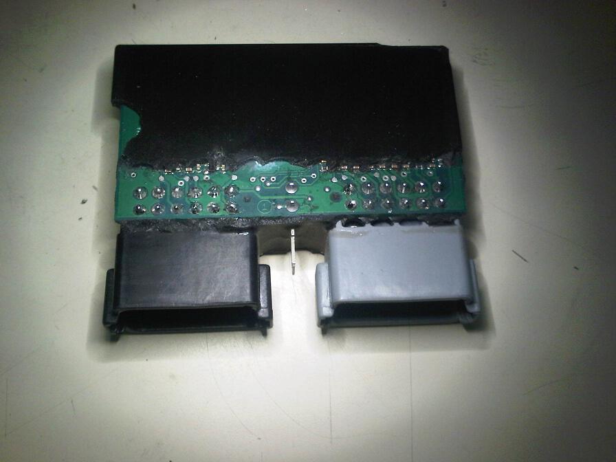 I am stunned for words!!! What a piece of fu+king junk. Its no wonder people have ECM problems. Not good enough for a bike. The first problem it that the connector blocks should be mounted/bolted to the PCB and NOT via the block pins. This stops stress to the solder joints. The second is that the whole unit should be encased in a solid block of "semi-hard" resin to cut out vibration and moisture getting to the unit. Also the joints are WAY to close to the front edge of the PCB. It should be about the same as the side. Say about 5 mm from the joint center to the edge of the PCB and the board about 2 mm thick. Those joints are machine made and that "dome" shape does not look right to me. Even with modern solder they should have a "shiny" finish to them. That "matt" look to the solder always indicates a "dry" joint caused by an incorrect temp of the solder/flux problem. This a very badly designed and built product. One of the worst I have ever seen. (Message edited by uly_man on March 30, 2012) (Message edited by uly_man on March 30, 2012) | ||
Blitzer454 |
Does anyone know if ECMSPY can reprogam one of the preprogrammed race ECM's from EBR? From their website it appears that I would need to buy a special programming cable which costs way to much. I did a TPS reset and the bike has been running flawlessly ever since. I did notice that when I went to reset the TPS that my TPS was set to 5.1%. I'm thinking last time I reset the TPS I must have set it too tick over but then never increased the idle to just over 1000 RPM. I ride with ear plugs almost all the time so it's conceivable that I didn't hear the low idle. I think I'm going to put the race ECM back in again just to make sure I wasn't running the engine at too low of an idle the entire time. But for now I'm going to just keep using the old ECM to get a better feel for how it behaves. uly_man, I think your right on the spot about the connector needing to be mounted better. However I think the real problem is the solder. If they simply would have used a solder with more flexibility this problem would not exist. I wouldn't be surprised if there are reports about bad ECM's from people that swear the seat is not making contact with the connector. As I suspect the engine vibration transmitted down the wire to the connector would be enough to eventually cause the solder to crack and fail. | ||
Teeps |
My 2 cents is the failure is caused by thermal cycling. It is a fairly common failure with solder joints (of input/output terminations) in ECMs' of all descriptions in the automotive world. The soldering of the terminals could be better too. A good manual reflowing of the solder on those pins should restore normal operation... I'm in the process of doing mine. | ||
Uly_man |
"However I think the real problem is the solder. If they simply would have used a solder with more flexibility this problem would not exist." No stress AT ALL EVER should be allowed to act on a solder joint on anything. The joint is not designed to do so and it WILL fail at some point. "My 2 cents is the failure is caused by thermal cycling." This can/does happen but mostly only after a long time. Like years. I have seen many ECUs (cars and bikes) and I have never seen one as badly designed as this. It looks like just removing or re-fitting the plugs could put stress on the board and damage it. Its just a nasty piece of crap and something that anyone who knows about bikes would have done something about, along with a few other things as well. (Message edited by uly_man on April 03, 2012) | ||
Hughlysses |
VERY good thread and something that will probably come in handy for just about all of us eventually. Uly_man makes a very good point that the connectors should be physically solidly mounted so that no stress from the cables is imparted to the solder joints. It seems a good project would be to mount the entire ECM on something like a sheet of 1/8" thick steel, large enough to cover the bottom of the ECM and the two connectors. Then the whole business could be potted so that the connectors and ECM were one, big solid block. Alternatively you could probably strap the connectors down to the plate with a metal bar mounted above them and screwed to the plate below. | ||
Garrcano |
Thank you Blitzer for your foregoing work. Opened:  Closed after repair: 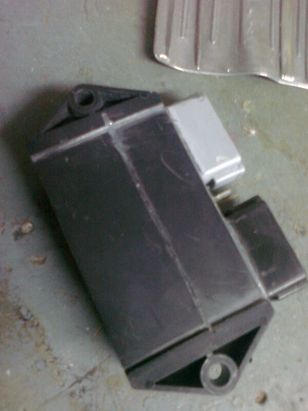 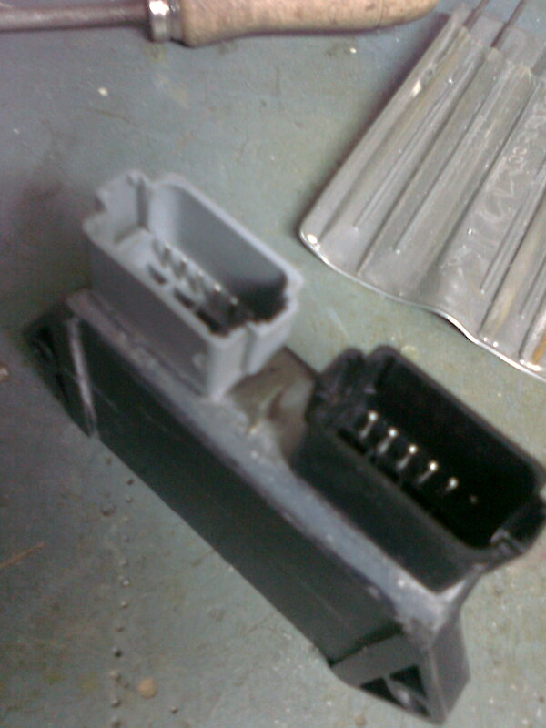 | ||
Etennuly |
Do you suppose this could be the reason for the two year fight that some of us went through with the 'flashing light/run/skip/fan not running' problem? My Uly has run excellently ever since that fateful day on the way home from 'Homecoming 2010' where I got pissed and cut the fan wire making it manually switched. The ECM apparently was not controlling the fan as it should have and even changing the ECM with a known good one did not help. I even have two seat spacer blocks to keep the seat off from the plugs. Thanks for posting this. | ||
Teeps |
Etennuly Posted on Tuesday, April 10, 2012 Do you suppose this could be the reason for the two year fight that some of us went through with the 'flashing light/run/skip/fan not running' problem? Yes. Pinging too, maybe... | ||
Xbimmer |
Etennuly Posted on Tuesday, April 10, 2012 Do you suppose this could be the reason for the two year fight that some of us went through with the 'flashing light/run/skip/fan not running' problem? Yes. Pinging too, maybe... Both those issues disappeared from my '06 when my ECM crapped out and I replaced it with one from an '07. Lost some MPG but who cares, it never ran so well before the swap even when new. Glad I kept the old one, this is probably what's wrong with it since it got to the point I could shut the engine off my pushing lightly on the connectors. | ||
Blitzer454 |
Garrcano, I like the way you sliced the case to get to the back of the connector. Looks nice and clean. I hope you were real careful not to cut down into any components on the board. The bad connection can cause a wide variety of different problems. It is likely that people will have different pins on the connectors that make a bad connection resulting in different bike problems. If the problem is intermittent this would be the first place to look. | ||
Garrcano |
... I hope you were real careful not to cut down into any components on the board... Yes I was.  Earlier I tried to open the ECM without destroying it. But I don�t like to disassemble anything which I couldn't see. That's why I thanked you, because you gave me the location of the connections and the boards. | ||
Etennuly |
Back in the days of my fan failure, I swapped my ECM for a known good one. The result was sameness. Interesting. | ||
Etennuly |
I have to ask.....is that gold solder on the original boards? | ||
Blitzer454 |
No, just bad camera lighting. | ||
Crackhead |
The dull finish is the result of applying a clear insulation "paint" to the board. | ||
Uly_man |
"The dull finish is the result of applying a clear insulation "paint" to the board." Interesting. What is this paint insulating against. |