G oog le BadWeB | Login/out | Topics | Search | Custodians | Register | Edit Profile


Buell Forum » Big, Bad & Dirty (Buell XB12X Ulysses Adventure Board) » BB&D Archives » Archive through February 01, 2010 » Dumb electrical question « Previous Next »

Author Message
Top of pagePrevious messageNext messageBottom of page Link to this message

Ratbuell
Posted on Sunday, January 17, 2010 - 07:11 pm:   Edit Post Delete Post View Post/Check IP Print Post    Move Post (Custodian/Admin Only)

I hate asking this...but I lost my Radio Shack "engineers book" or whatever it was called years ago. I used to be able to recite this stuff off the top of my head...but I think I must have drowned those brain cells ; )

I've got a momentary pushbutton switch.

I want to wire up a lighting circuit on my Uly.

What do I need - and schematics / part numbers / tech talk are perfectly acceptable - in order to let this momentary switch turn a 12v circuit on with one push/contact, and off with a second push?
Top of pagePrevious messageNext messageBottom of page Link to this message

Mikef5000
Posted on Sunday, January 17, 2010 - 07:28 pm:   Edit Post Delete Post View Post/Check IP Print Post    Move Post (Custodian/Admin Only)

Latching relay sounds like what you want:


quote:

Latching relay
Latching relay, dust cover removed, showing pawl and ratchet mechanism. The ratchet operates a cam, which raises and lowers the moving contact arm, seen edge-on just below it. The moving and fixed contacts are visible at the left side of the image.

A latching relay has two relaxed states (bistable). These are also called "impulse", "keep", or "stay" relays. When the current is switched off, the relay remains in its last state. This is achieved with a solenoid operating a ratchet and cam mechanism, or by having two opposing coils with an over-center spring or permanent magnet to hold the armature and contacts in position while the coil is relaxed, or with a remanent core. In the ratchet and cam example, the first pulse to the coil turns the relay on and the second pulse turns it off. In the two coil example, a pulse to one coil turns the relay on and a pulse to the opposite coil turns the relay off. This type of relay has the advantage that it consumes power only for an instant, while it is being switched, and it retains its last setting across a power outage. A remanent core latching relay requires a current pulse of opposite polarity to make it change state.


Here's a way to make your own:

quote:

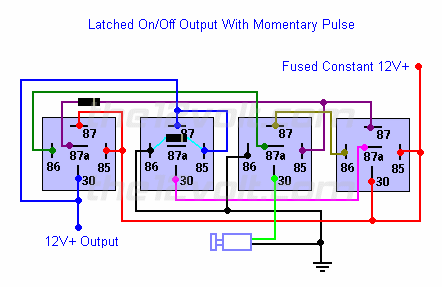
Latched On/Off Output Using a Single Momentary Pulse (link)
Similar to the momentary to constant configuration above, we can engage and disengage the latched output with a single pulse from a switch or an output from an alarm or remote keyless entry. The first pulse from the switch will engage the latch. The next pulse from the switch will disengage the latch.


quote:

Here's the same configuration as the one above that you can use if you do not have any *diodes available and/or only want to use SPDT relays. A negative output from an alarm, remote keyless entry, or other device can be used in place of the switch shown in both of these diagrams.


Info stolen from wikipedia.com and the12volt.com
Top of pagePrevious messageNext messageBottom of page Link to this message

Ratbuell
Posted on Sunday, January 17, 2010 - 11:22 pm:   Edit Post Delete Post View Post/Check IP Print Post    Move Post (Custodian/Admin Only)

Perfect! Thank you : )
Top of pagePrevious messageNext messageBottom of page Link to this message

Froggy
Posted on Sunday, January 17, 2010 - 11:49 pm:   Edit Post Delete Post View Post/Check IP Print Post    Move Post (Custodian/Admin Only)

Speaking of that book, I know what it is, I have seen it on Mythbusters, what is it called? I need to order one.
Top of pagePrevious messageNext messageBottom of page Link to this message

Ratbuell
Posted on Sunday, January 17, 2010 - 11:54 pm:   Edit Post Delete Post View Post/Check IP Print Post    Move Post (Custodian/Admin Only)

I wanna say it was "engineers mini-notebook" or something similar. It was a RadioCrack...er, Shack publication IIRC.

Mythbusters. Where'd I go wrong with my career choice? *I* should be doing that for a living!
Top of pagePrevious messageNext messageBottom of page Link to this message

Froggy
Posted on Monday, January 18, 2010 - 12:06 am:   Edit Post Delete Post View Post/Check IP Print Post    Move Post (Custodian/Admin Only)

Ah, found it from Google

http://www.amazon.com/gp/product//1885071337/ref=c m_aya_asin.title/103-5718971-3362230?ie=UTF8


quote:

Oh sure, you can get most of this information off of the internet. But out in Hooterville at O-dark-thirty, you may be able to find your answer before your alpha-geek friend has even accessed the 'net.


I am calling BS there, I have gotten Buell wiring diagrams off the web on a moments notice before : D


Is that the same book you were talking about Rat? If not, it sounds like it would be good to have anyway.
Top of pagePrevious messageNext messageBottom of page Link to this message

Reepicheep
Posted on Monday, January 18, 2010 - 12:21 pm:   Edit Post Delete Post View Post/Check IP Print Post    Move Post (Custodian/Admin Only)

If you want the electronics to be all low power, you can use a flip flop, driving the base of a transistor, that runs the relay coil.

http://en.wikipedia.org/wiki/Flip-flop_%28electron ics%29
Top of pagePrevious messageNext messageBottom of page Link to this message

Ratbuell
Posted on Monday, January 18, 2010 - 07:47 pm:   Edit Post Delete Post View Post/Check IP Print Post    Move Post (Custodian/Admin Only)

Frog - that's close, but I want to say mine was maybe 3x5", green cover and spiral bound. More like a recipe book.

'course, at my age....that was a lifetime ago in publishing (and electrical engineering) terms LOL.

Reep - what I'm looking to do is use a momentary switch to latch on (turn on) a lighting set. I'll be running all LED's (trying to conceptualize a hazard setup for the Uly with some TIR3 cop lights), so low-draw...but all 12v.
Top of pagePrevious messageNext messageBottom of page Link to this message

Sekalilgai
Posted on Monday, January 18, 2010 - 07:59 pm:   Edit Post Delete Post View Post/Check IP Print Post    Move Post (Custodian/Admin Only)

Joe
I remember the books, maybe that says something about my age! 'The Shack' is pretty much Radio Crap these days.

If you had the lo-hi wired (on a ignition hot circuit) together you might consider stealing the 'real' hi-beam circuit for your aux. I'd use the flash-to-pass to trigger(and latch) the relay (and latch). There aren't enough discrete wiring stock but a few more wires shouldn't be too much trouble. Once latched though, the only way to de-energize the latched relay is to bring it back to 'low beam'. This assumes a separate blinker for the hazards and that you're ok with wiring lo-hi together. One relay and a few wires to bust out the flash circuit.

Alternatively you could power the flash-to-pass switch (and relay) from low-beam and toggle to high to reset your hazards.
Top of pagePrevious messageNext messageBottom of page Link to this message

Ratbuell
Posted on Monday, January 18, 2010 - 09:14 pm:   Edit Post Delete Post View Post/Check IP Print Post    Move Post (Custodian/Admin Only)

Nah. Already got a dedicated switch - got a pursuit pushbutton from an XP : ) Mounts to the master cylinder clamp bolts, sits at the RH thumb, and the pigtail goes to the flyscreen where I need to make my connections. I'll probably just extend back to under-seat, and put the relay(s) either under-seat or under-tail (between taillight and license plate).
Top of pagePrevious messageNext messageBottom of page Link to this message

Reepicheep
Posted on Monday, January 18, 2010 - 09:19 pm:   Edit Post Delete Post View Post/Check IP Print Post    Move Post (Custodian/Admin Only)

In that case, you can probably drive the LED's off a bigger transistor. I'll try and do some math tomorrow and see what I can work up...
Top of pagePrevious messageNext messageBottom of page Link to this message

Sekalilgai
Posted on Monday, January 18, 2010 - 10:02 pm:   Edit Post Delete Post View Post/Check IP Print Post    Move Post (Custodian/Admin Only)

gotcha, just seems like a 4 or 5 relay approach is a bit much. Latching is easy, the reset bit without a bunch of other relays gets tricky. Consider reset with ignition off? No added relays that way.
Top of pagePrevious messageNext messageBottom of page Link to this message

Ronmold
Posted on Monday, January 18, 2010 - 11:07 pm:   Edit Post Delete Post View Post/Check IP Print Post    Move Post (Custodian/Admin Only)

This relay would do it:
http://www.newark.com/magnecraft/711xbxcl-12d/alternating-load-relay/dp/10M6472
I got all those old 'Shack books


Top of pagePrevious messageNext messageBottom of page Link to this message

Sekalilgai
Posted on Monday, January 18, 2010 - 11:25 pm:   Edit Post Delete Post View Post/Check IP Print Post    Move Post (Custodian/Admin Only)

neat! I learned something new...I was only aware of the latching with reverse polarity toggle type.
Top of pagePrevious messageNext messageBottom of page Link to this message

Go2
Posted on Tuesday, January 19, 2010 - 08:31 pm:   Edit Post Delete Post View Post/Check IP Print Post    Move Post (Custodian/Admin Only)

My head is flip floppin with semicoinductors!
I have a hopeful idea, but No Uly wiring diagram here to confirm my hopes!
On a BMW you could push the turn signal cancel switch to produce your flipflop ground pulse!
Does a ULY have is a turn signal cancel switch that sends a ground back to blinker circuit? If Yes! take a peek at the AUTOSWITCH 4NB
http://www.autoswitch.com/as4nb-Install.htm
Sorry if this turns out to be a wild goose chase.
Top of pagePrevious messageNext messageBottom of page Link to this message

Natexlh1000
Posted on Tuesday, January 19, 2010 - 09:39 pm:   Edit Post Delete Post View Post/Check IP Print Post    Move Post (Custodian/Admin Only)

The turn signal cancel button is mechanical.
Try it when the bike is off.

Perhaps the flash to pass trigger can be hijacked away from the high beam?
Top of pagePrevious messageNext messageBottom of page Link to this message

Go2
Posted on Wednesday, January 20, 2010 - 02:11 pm:   Edit Post Delete Post View Post/Check IP Print Post    Move Post (Custodian/Admin Only)

Can anyone round up a wiring diagram for me to look at? I want to use exsisting switches to trigger external relays for lights, garage door opener, whatever.

tnx
Top of pagePrevious messageNext messageBottom of page Link to this message

Ronmold
Posted on Wednesday, January 20, 2010 - 07:44 pm:   Edit Post Delete Post View Post/Check IP Print Post    Move Post (Custodian/Admin Only)

What year is your Uly?
Top of pagePrevious messageNext messageBottom of page Link to this message

Go2
Posted on Thursday, January 21, 2010 - 08:57 pm:   Edit Post Delete Post View Post/Check IP Print Post    Move Post (Custodian/Admin Only)

Ronmold,

I own a 2007 xb12x.

j
« Previous Next »

Add Your Message Here
Post:
Bold text Italics Underline Create a hyperlink Insert a clipart image

Username: Posting Information:
This is a private posting area. Only registered users and custodians may post messages here.
Password:
Options: Post as "Anonymous" (Valid reason required. Abusers will be exposed. If unsure, ask.)
Enable HTML code in message
Automatically activate URLs in message
Action:

Topics | Last Day | Tree View | Search | User List | Help/Instructions | Rules | Program Credits Administration