| Author | Message | ||
Johnboy777 |
What's the best way to route my fog light wires from the battery to the front headlight bracket?? I ditched the PIAA harness (too flippin' balky) and went to West Marine for some 14ga. marine grade wire and a 10Amp in-line fuse and relay. I would like to stay as close to the main loom as I can, but that doesn't seem possible - engine heat's an issue too, I imagine. The air cleaner housing seems like a possibility. Anyway, thanks. 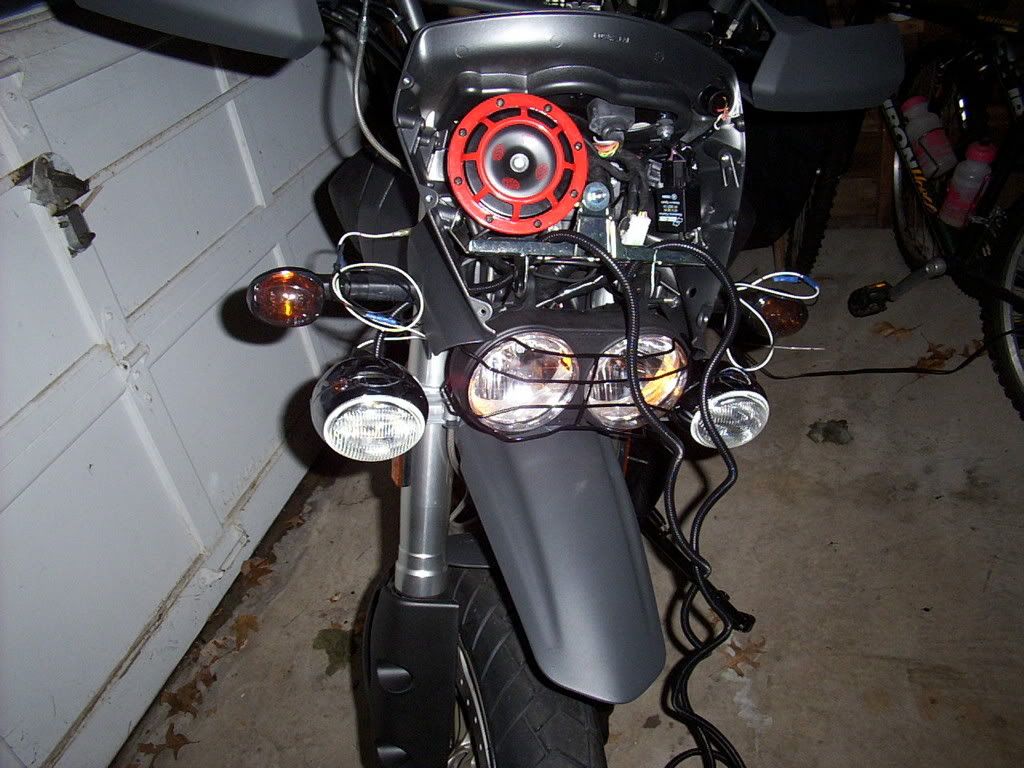 . | ||
Ft_bstrd |
I ran mine with the main wiring loom. It runs under the airbox base plate and out the left side and into the front fairing. I would recommend loosening the airbox base plate. At the time, mine had about 18lbs of loctite and I couldn't get all the screws loosened. So far, I haven't had any problems. I would recommend using a relay for sure. | ||
Nopork |
I ran mine as Ft_bstrd did, along the main harness. I removed the lower air box cover altogether, and it made things a lot easier. My screws were loctited to be heck also. Just make sure if you remove the air box lower cover you get the flange around the velocity stack back on correctly and the two rubber hoses by the air sensor only sticking out about 1/2" through the box. The shop manual says they should not extend beyond the air sensor inside the air box. Watch how high they are before sliding them out through the air box bottom. I used the regular PIAA harness and just doubled it up on itself under the air box and cable tied it to the frame by the main harness. | ||
Johnboy777 |
Thanks FB, sounds like a plan. BTW, I was also thinking, that it would be easier just drilling a tiny hole in the frame, then fish the wire through and drill another tiny hole up front, and feed it through. . | ||
Florida_lime |
You mean drill a hole in your gas "tank" ?  | ||
Jlnance |
You don't need to drill holes. You can run the wires out from the under the seat area by running it through the same hole the transmission vent hose comes through. | ||
Reepicheep |
Thats what I did as well. Working fine. | ||
Ft_bstrd |
I am actually going to relocate my HID ballast unit into my airbox void to clean up the front fairing area to make room for a better horn. I also plan on adding a second HID kit in super yellow and won't have room in the front. I will run the hot wires from the relay attached to the rear power plug and battery up to the airbox and then run the wires from the igniter to the ballast so that everything meets in the middle. | ||
Johnboy777 |
I've got it ... just run it next to the plastic conduit (main loom) that runs along the frame rail. At first I thought heat from the cyl heads would be an issue running it there - but i guess not. Thanks | ||
Reepicheep |
Thats what I did Ft. You have the right idea running all the wiring out the back of the airbox base plate. I just had to rotate my engine down, and the fact that the wires were in the back and not the front let me leave everything hooked up, and just flop it 180 degrees over and leave it where the seat used to be. | ||
Treadmarks |
I installed an aux fuse panel under the seat near the seat latch, wired directly to the battery. Then ran dedicated high, low and horn in 14 gauge from the aux fuse panel under the airbox base to the cowl inside of a flexible heat shield. The relays for both headlights and horn are located under the front cowl. The fuse box I used has expansion slots for other devices, and I just added a cable for my electric vest connection. The lights were considerably brighter after the relay installation. 260 watts was too much for the factory wires and switches. The aux fuse panel is grounded to the battery and frame and I installed a #4 hi flex ground strap to the factory steering neck grounding point, then ran it into the cowling as a common grounding post. This eliminates the need to run multiple ground cables back to the battery. The green/blue cable on the left is the ground strap. I know it is a huge overkill, but is very light, flexible and free.  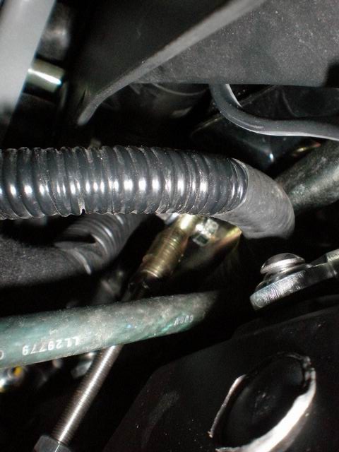 | ||
Jflaig |
I followed the others' pattern of following the main harness. I tucked the PIAA relay between the battery and the fuse block. Just zip tie the wires to the harness to ensure that it stays high. The air box base tray is a PITA, but you need to get used to going under it. | ||
Xbimmer |
The air box base tray is a PITA, but you need to get used to going under it. +1. Lots of stuff under there that can cause grief if not examined occasionally. Treadmarks, I've been thinking of something like your ganged arrangement also, just to keep the battery connections simple. Got a pic? | ||
Ft_bstrd |
I'm afraid of pictures of gang "arrangements". | ||
Xbimmer |
I expect you would be Ft-b, knowing of your penchant for exploring the unknown where the rest of us fear to tread...   | ||
Ft_bstrd |
 | ||
Ulyessesman |
ne 1 here? | ||
Jlnance |
I found my writeup: http://www.badweatherbikers.com/cgibin/discus/show .cgi?tpc=37&post=817006#POST817006 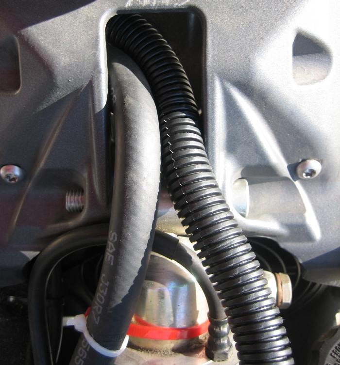 | ||
Treadmarks |
Treadmarks, I've been thinking of something like your ganged arrangement also, just to keep the battery connections simple. Got a pic? Try these. Here is a shot of the fuse panel in the back. 12 wire going in, with 14 going out. First two are for the deathray, then the horn, followed by the electric vest. 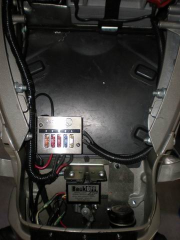 The wire harness then follows the left side frame rail and slips under Odie's blankets, which have been modified to tuck under the bas and ecm to keep the engine heat away from the electrics. 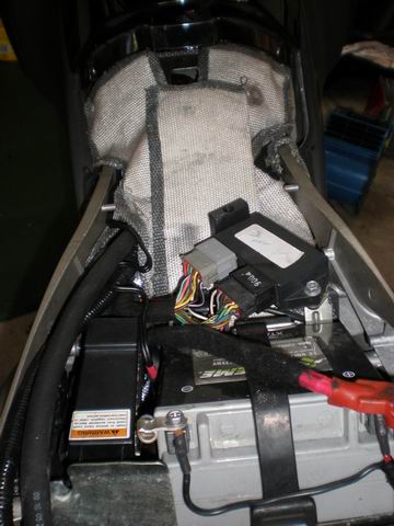 Under the heat blankets, you can see the harness following through the hole behind the base of the air box where they travel along the inside of the left side frame rail paired with the stock harness. 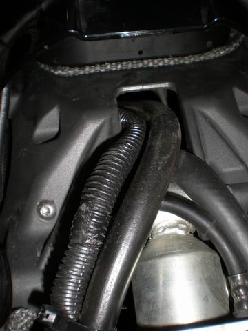 In this shot, you can see the #4 ground cable snaking from the steering head mounting point up through the hole in the factory cowling crossbrace. Also notice the independent headlight adjustment rods as well as the antivibe rod connecting the cowling crossbrace to the lower tree. 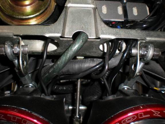 Here is the floating grounding post in the center hole of the cowling crossbrace. The horn mount, lighting relay mount and all grounding wires in the cowling are connected to this post. 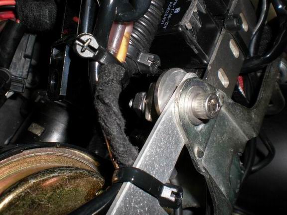 Just a quick shot of the lower mount of the antivibe rod where it attaches to the lower tree and top of the front fender. 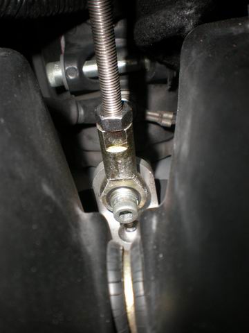 | ||
Xbimmer |
Great Treadmarks, thanks!  Where'd you get the junction box, looks like it might even fit where you've located your XP. I put my XP on the left subframe rail so I have room there behind the latch, which would still leave me room forward for my Buell underseat thing. I also like what you've done with Odie's blankets to isolate the electronics, never made sense to me to cook them with the stock setup...  | ||
Johnboy777 |
Treadmarks & Xbimmer, With regard to the blankets, don't they restrict air flow off of the fan/rear cyc.? | ||
Ft_bstrd |
Their is a LARGE hole in the rear section through which the air flows. Most of the air pushes past the rear shock. This is really just meant to keep the heat off of the bottom of the seat pan. | ||
Michael1 |
I ran mine next to the main wiring harness and wrapped it with some heat tape as it went by the rear cylinder head. I used the PIAA harness but I chopped it down quite a bit. I have the relay up front in the fairing with the fuse out back next to the battery. So far it works for me. |