| Author | Message | ||
Kls |
I installed the Stebel Nautilus Compact Air Horn on my XB12X today. It fits behind the windscreen without cutting or removing anything except the OEM horn. Getting it into the windscreen area is easy. All the work comes from prepping and routing the wires. 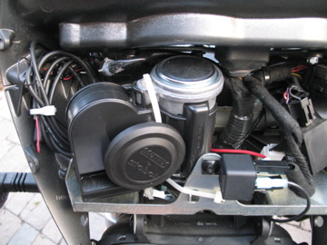 That bundle of wiring to the right side of the bike is from my GPS installation; you probably won't have it there to get in the way. I got the Stebel on eBay using the Motorcycle Safety Store (http://stores.ebay.com/Motorcycle-Safety-Store) for less than $50 shipped. They included a kit with everything I needed to install the horn--relay, wiring, fuse, and connectors. I deviated slightly from their printed instructions but it's all explained below. I have no interest in that business but I can tell you for sure that they include all the kit parts needed to install the horn. Tools needed: Philips screwdriver for battery terminal Torx 27 for intake cover & airbox Torx 25 for windscreen & horn 7/16" wrench for horn Crimping tool Wire cutters 1/4" drill bit & drill Parts needed: (all included in the horn kit I bought) Fuse holder for 20A fuse At least 4' of red 14-gauge wire 2' of black 14-gauge wire 4 insulated push-on 0.250 blade terminals, 14-gauge 1 ring terminal, 14-gauge 1 spade terminal, 14-gauge 1 insulated bullet connector (optional) Soldering iron & solder (optional) Remove the 6 bolts holding the windscreen and set the windscreen aside. Remove the OEM horn. Keep the horn's mounting nut & bolt handy because you'll use them again. Remove the 4 bolts for the intake cover ("tank" cover) and set the cover out of the way. I say this because you don't want to set it down next to the bike and then step on it. There's a gas tank vent hose that runs over the top of the airbox cover. Pry it off the vent fixture but don't remove it from the airbox groove. Remove the airbox top cover by opening the 6 latches. Let the cover hang loose on the left side of the bike. Remove the air filter. Remove the 4 bolts holding the airbox base. Mine must have been installed with high-strength (red) loctite and were very hard to break loose and unscrew. Use a GOOD Torx wrench or you'll ruin the heads of the bolts. Lift the rear of the baseplate slightly. From below, pull out the left-side vent hose from the baseplate. (This short hose is connected to the rear cylinder head.) You CAN'T push it down from above. That just squashes the hose and it won't fit through the hole. It's pretty easy to wriggle the hose out from below. Pull the baseplate over the velocity stack, and let it hang loose on the right side of the bike. Caution: In these next steps, my kit included BARELY enough red wire to reach from the fuse to the battery. If you have the kit, don't make a mistake with the red wire or you'll need to get more. (There's a last-chance tip later, but it's not pretty.) Note that I installed the relay up front, close to the horn. The kit instructions say it should be close to the battery, but that means you'll have to cut and lengthen both OEM battery wires and then run them from the front of the bike back to under the seat. My way is easier. Crimp the ring terminal onto one end of the red wire from the fuse (kit included fuse with wire leads). DO NOT yet connect that to the battery or you'll be routing a live wire past metal frame pieces--Zap! It doesn't matter which way the fuse is oriented, but I installed mine with the top of the fuse holder connected to the battery; it makes replacing the fuse a bit easier. Connect the opposite end of the fuse holder to the long piece of red wire. You can make a spliced connection or solder it, but I chose to use an insulated bullet connector "just in case". It actually turned out good that I did so since it gave a little extra length that I needed at the front of the bike. 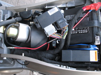 I ran the fuse under all the wiring for the terminal block because I thought it looked cleaner. There's no other reason to do so; leaving it on top actually makes fuse replacement easier. Route the red wire from under the seat to the horn. You can slip this under the left side of the cross rail by sliding it along the existing wire bundle. 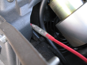 Then route it inside the frame rail, on top of the plastic holder for the wire bundles. If you have the kit wire, route it inside--to the right of--the two hoses that hang inside near the headstock. (Are you getting the impression that the kit's red wire has no extra length??) Bring it under the headstock, slip it through the factory zip tie, through the plastic holder at the front of the steering stem, then into the center of the windscreen area. 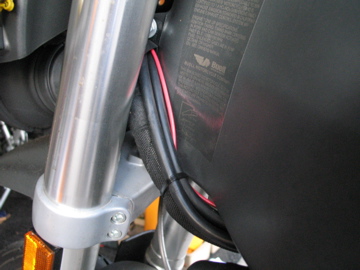 It should reach past the OEM horn mounting bolt. If not, take about 2" of the black wire and use it to extend the red wire. (I warned you that it wouldn't be a pretty solution if you ran out of wire.) Crimp a blade terminal onto the front end of the wire. I'll still be calling this the red wire. Use the 1/4" drill bit to enlarge the mounting hole on the relay, and use the OEM nut & bolt to attach the relay onto the OEM horn's mount. Don't tighten the nut completely. The relay should be horizontal, pointing to the bike's left side. 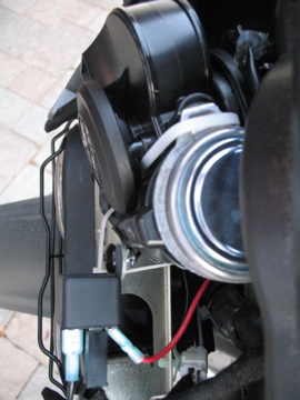 Cut a piece of black wire about 6" long. Crimp a blade terminal to one end, and the spade terminal to the other end. Slip the spade terminal under the nut for the relay mounting; the spade terminal should be pointing down. Tighten the nut. This will connect to the horn and makes the OEM bracket act as ground, but it's a good ground. Cut a piece of black wire about 9" long. Crimp the last two blade terminals to each end. Connect one end to the relay. In my case, this was the front blade of the relay. Attach both OEM horn wires to the relay. The yellow/black wire should be on the bottom blade of the relay, the black wire on the top blade. Connect the red wire (from the fuse) to the brass blade of the relay (in the back of the relay). I chose to VERY CAREFULLY bend the tab back slightly so there would be less strain on the fuse wire. See the top view, above. Get the horn (finally!) and connect its positive terminal (right one as the horn is facing you) to the long black wire that runs over to the relay. In my case, I ran this wire through the center of the OEM bracket and around the back. Once the horn is installed, this wire is behind the bracket, so you want to route it that way to start with. Connect the horn's negative terminal (left one as the horn is facing you) to the short black wire from the relay's mounting bolt. I first routed this behind the relay. Carefully place the horn into the windscreen area, sliding it in from the bike's right side. You may need to push the OEM wiring back so it's out of the way. Make sure that the horn's positive terminal and its connected wire are behind the OEM bracket, and that the negative terminal is in the middle of the bracket. Be sure the wire on the negative terminal clears the bracket. 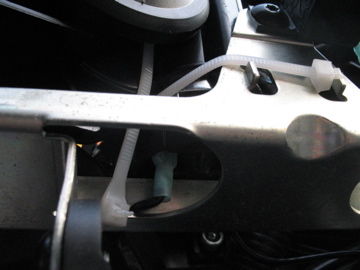 The horn needs to be pushed to the center as far as it will go, otherwise it will interfere with the windscreen when you try to put everything back together. The horn's intake tube should be behind the OEM mounting tab. See the top view or front view, above. Fasten the horn securely in place. I used zip ties. I usually prefer using mounting brackets, but they would have involved much more work. Since the horn rests on the OEM bracket and the zip ties only serve to keep it from moving around, they should be fine. Attach the red wire to the battery's positive terminal. You can now turn on the ignition and test the horn. Hopefully, you get a LOUD blast. Be ready to release that horn button quickly! If the horn doesn't work, then you're on your own to figure out what you did wrong. Check the fuse. Go back through these instructions and double-check all connections. Install the windscreen. Take the airbox baseplate and push the hose back through it. I found it easier to start the hose through the hole, then use pliers to pull it the rest of the way. Slip the baseplate over the velocity stack. The baseplate should fit between the upper and lower sealing rings on the velocity stack's base. Install the four Torx bolts, using red loctite. Tighten to 84-120 in-lbs. Replace the air filter and top cover of the airbox. Snap the 6 latches to secure the top cover. Stretch the gas vent hose forward and slip it onto the gas vent fixture. Install the intake cover. Take a long ride, waiting for someone to make a foolish move so you can blast the...heck...out of them. After taking these photos, I inserted a piece of foam between the horn and the vertical part of the OEM bracket to keep the bracket from wearing through the horn's intake tube. | ||
Thesmaz |
Thanks for the ebay link! Nice write-up and pics. I have been planning on upgrading the horn but just haven't done it yet and I was looking at one of these horns. I'll just add it to my winter time list of things to do. | ||
Too_tall_todd |
wow great thread, I am also looking forward to upgrading my horn. My concern was to place such a loud horn under the windscreen, does that placement cause the energy/sound to mostly resonate the fairing. might be louder for the driver then who you are honking at. if you could tell us how it works I know that I would appreciate it thanks again T3 | ||
Captainxb |
T3, these horns are so darn LOUD that EVERYBODY can hear it!! Most of the sound goes out through the bottom of the dash area, past the headlights. One of the best safety mods you can do. | ||
Kls |
The horn's a lot louder than the stocker, but doesn't blast the rider. Sure, it would be better if it weren't behind the screen, but the open mouth has to be protected from rain so if it wasn't behind the screen it would have to be hidden someplace else--and probably someplace worse than this. | ||
Javadog |
Couldn't you saw a big old blowhole in the screen and cover it with some sort of fine acoustically transparent water resistant material? Come on, there have to be several acoustical engineers in this crowd!! | ||
Andrejs2112 |
Thanks for the thread.The instructions made this so simple. For any others doing this install, pay CLOSE attention to the relay pin-out that comes with the instructions. I blew a fuse making the wrong connections to the relay. I must have gotten a different relay with my kit. |